

Browse All Articles > Understanding Network and Internet Latency
Many network operators, engineers, and administrators do not take several factors into consideration when troubleshooting network throughput and latency issues. They often measure the throughput by performing a measurement by transferring a large file and measure the time it takes to transfer that file; however the results will result in what is called goodput which is less than the maximum throughput, leading the operators to believe that their link is not operating as it should be. In fact, there are many overheads and other variables involved.
The actual throughput for a transmission link in any network utilizing TCP/IP depends on a number of factors:
* Network Latency (End to End)
* Link Speed (bps)
* Propagation, Serialization, and Queuing delay
* Window size (RWIN), window scaling and CTCP
* Network Congestion
* MTU/MSS
* Protocol Overhead (Layer 2, 3, and 4)
* Ethernet Efficiency
* Link reliability
The Good, the Bad and the Ugly:
There has been much heated debate, relaxed discussions, and great articles written (Great article 1 and Great article 2) on enabling jumbo frames for network communications (typically the Internet); the majority of Internet traffic is HTTP, so utilizing jumbo frames has no real benefits from this perspective as the average packet size for HTTP traffic can vary from 64 bytes to 512 bytes. We are not going to get into the details of jumbo frames, cause at this time, the standard is still 1500 bytes for your MTU; however, some ISPs are utilizing jumbo frames on their 10Gbps backbone and in some cases, back-end networks for database replication, file replication (NFS) for better efficiency and performance.
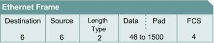
Your typical Ethernet frame will have a format such as in Figure 1 (assuming no VLAN tag).
Fig. 1
![Frame01]()
Take note of the size of each block (excluding the DATA block):
this equates to Ethernet overhead of 18 Bytes (6+6+2+4=18).
With a VLAN tag you will have an additional 4 bytes for a total of 22 bytes of overhead.
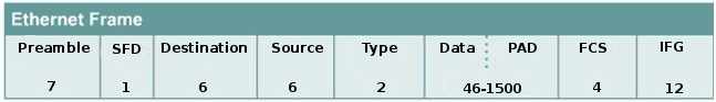
What is important to note, there is another important factor missing in FIG. 1; for each frame that is transmitted on the transmission medium (cable or fiber) there is a preamble and a inter-frame gap (IFG), review Fig 2..
Fig.2
![Frame02]()
The preamble and IFG are mandated which occupies an additional 20 bytes (8+12=20) of overhead. This is important because when you are calculating Ethernet frame efficiency on a network, you must include this in your calculations. Why? Well it is built into the Ethernet specification; this is true for 10/100/1000/10000 Ethernet.
Before, we can continue, I need to discuss MTU and MSS a bit; again, I will not go into much detail as you should have the basics down. MTU (Maximum Transmission Unit) is often referred to as the packet size and is the greatest amount of data that can be transferred in one physical frame on the network. The actual data is referred to as MSS (Maximum Segment Size), which defines the largest segment of TCP data at layer 4.
Assuming for the sake of this next example that I was sending you nothing but 64 byte frames on a 100Mbps network (NICs and switches), as I explained above that smaller frames are not very efficient; In this example, the 64 byte frame has already included the Ethernet headers, so the actual IP payload is 46 bytes.
So how efficient are 64 byte frames?
How many 64 byte frames can I send per second on a 100Mbps link?
The answer is 148809.5 pps.
We have a 100Mbps network = 100,000,000 bits per second (100000000bps)
Since we are working with bytes, we will need to convert from bits to bytes. Since there are 8 bits to a byte, we will need to divide the bits by 8 bytes:
So, to answer the first question, how efficient are 64 byte frames in a network:
Layer 2 has about 45 percent of overhead utilizing 64 byte frames
* 23.8 percent of overhead is consumed by the preamble and IFG: (20 bytes)
PPS x Frame Size x 8 = bps/bandwidth = percent
148809.5 * 20 * 8 = 23169520/100000000 = 23.8 percent
* 21.4 percent of overhead is consumed by Ethernet header and trailer (18 bytes)
PPS x Frame Size x 8 = bps/bandwidth = percent
148809.5 * 18 * 8 = 21428568/100000000 = 21.4 percent
Which only leaves 54 percent of IP payload. This of course is not very efficient.
What about 1500 byte frames?
What kind of throughput can I expect with TCP utilizing 1500 bytes
If you review the RFCs for IPv4 and TCP (RFC791 and RFC793), they include the size of the headers for the protocols:
RFC791: Figure 4
Version, IHL, TOS, total length is a total of 4 bytes
ID, Flags, and Offsett is a total of 4 bytes
TTL, Protocol, an checksum is a total of 4 bytes
Source address is a total of 4 bytes
Destination address is a total of 4 bytes
For a total of 20 bytes of IP overhead
RFC793: Figure 3
Without getting into too much detail, just know that before the options in TCP, total bytes are 20 bytes; this is layer 4 overhead. If you include the timestamp option, it is an additional 12 bytes; however, you will also notice
that options is a variable field that can be up to 44 bytes.
Assume we are downloading an ISO that is 4GB is size and that the MTU is 1500, circuit is 100Mbps and no timestamps are being used; remove all the overhead at layer 2, 3 and 4:
Get the packets per second for a 1500 byte frame
12500000 / 1538 = 8127.4pps
8127.4 * 1460 * 8 = 94.9Mbps would be your theoretical throughput for 1500 byte frames
2.4 percent of overhead at layer 2 for a 1500 byte frame
2.6 percent of overhead at layer 3 and 4 for a 1500 byte frame.
The combination of propagation, serialization, queuing often produces a complex and variable network latency profile. Serialization and queuing delay are very negligible on high speed networks, and at most are not included in any real calculations.
Serialization delay is the amount of time it takes for a networking device (such as a router) to encode a packet onto the wire for transmission. For example, a 1500 byte (12000 bits) packet transmitted over a T1 has a serialization delay of 12000 bits / 1536000 bits/sec = 7.8ms, the same packet on a Fast Ethernet circuit has a delay of .12ms. On a Gigabit Ethernet circuit, the delay is only .012ms.
Formula:
( MSS + header ) * 8 bits/byte
-------------------------------------------------- = Delay
link speed bits/sec.
So serialization is a factor for a T1 circuit; There is a fixed 7.8ms of latency (not very high, but high compared to Fast Ethernet, and is why serialization is not a major factor for high speed networks).
Routers can only process one packet at a time. If packets are arriving faster than the router can process them, the router will place the packets into the a queue, this is by definition Queuing delay. When discussing the utilization of a circuit it is important to discuss it using an average utilization over some unit of time;
example:
A 100Mbps circuit that is 70 percent utilized is 30 percent empty; 70Mbps utilized and 30Mbps available. This does not however, mean that the interface is 70 percent utilized, the interface is in use or it is not in use (100 percent utilized or 0 percent utilized). When a packet/frame arrives at a routers interface which needs to be routed out another interface, the router will forward/route that packet, but at that moment in time, the interface is 100 percent utilized. During the time that a interface is in use (100 percent utilized) and another packet arrives at the same time that the interface is in use, the packet must be queued by the router until the router has finished processing the first packet; then it can process the packet that arrived after the first; Most Internet backbone routers will not have any queuing delays unless the circuit is around 90 to 100 percent utilized (Considered congested).
Which now brings us to the most important one of all:
When PD (Propagation delay) is a consideration; PD depends on the speed of light; Is speed of light constant? Well, you can not make it go faster (Front Velocity); however, you can slow it down. In reference of space (outer space) light is the most effective, meaning that light travels the fastest in a vacuum which is roughly 186,000 miles per second. The index of refraction is a way of measuring how much the velocity of a wave is reduced inside a medium (Vacuum, fiber, glass, etc.). The larger the index of refraction is, the slower the light travels in that medium. Taking a known number: 186,000 miles per second, the index of refraction for light in a space is 1. You can calculate index of refraction of another material by dividing the speed the speed of light in a vacuum by the speed of light in another (n = c/v). The typical value for the core of a fiber is 1.48.
Remind you, this latency is fixed based on physics. It is there and will always be there.
Example:
What kind of propagation delay should I expect from Denver to Seattle?
In this example, we will use Level3's Network Map: Level3 Map
Per Google maps, the distance to Denver to Seattle is 1327 Miles.
* The distance from Denver to Seattle: 1327m
* The speed of light in vacuum is 186,000 miles/Sec (m/s).
* The speed of light in fiber is roughly 68% of the speed of light in vacuum. (n = c/v [1/1.48=.675]).
* The speed of light in fiber is 186,000m/s * 0.68 = 126,480miles/s
* The one-way delay to Seattle is 1327m / 126,480miles/s x 10^3 = 10.4ms.
* The round-trip time to Seattle from Denver and back is 20.8ms via Level3.
actual latency reported by ping is: 28ms (The difference of 20.8 and 28 is negligible)
There is some queuing and serialization delay, but this is very negligible.
What you want to consider here is very high latency where it is NOT expected; however, if you executed a traceroute to a destination and only one hop had high latency and the very next hop had a much lower latency, this does not necessarily indicate that there is an issue; the could be a result of how long it took the router to generate the ICMP exceed TTL message (Router is just busy with other important traffic, its concern is NOT ICMP, most cases ICMP is specifically rate-limited and de-prioritized). If there is an actual issue, the latency will continue or increase for all future hops afterward.
In simple terms; roughly, every 125 miles, you will have 1ms of latency (assuming no queuing or processing delays).
In TCP connections, the large Bandwidth Delay Product (BDP) of high latency connections, combined with relatively small TCP window sizes on many end systems, effectively causes the throughput of a high latency connection to drop sharply with latency and packet loss. This can be rectified with various techniques, such as increasing the TCP congestion window size; however, with many new operating systems, CTCP, Window scaling, and Receive Window auto-tuning, there is no need to manually set your RWIN settings. With autotuning, the receiver buffer size (and TCP window size) is dynamically updated (autotuned) for each connection. Older operating systems, some Linux 2.4 kernels, Windows 98, ME, 2000, and XP do not have RWIN Auto tuning or window scaling implemented, so it was/still is necessary to manually configure the RWIN values.
So what is the Optimum TCP window size? This depends on guess what? Latency! This is why the low RTT from point A to B is important!
Also, what is important to understand that packet loss is interpreted by TCP as network congestion, so TCP will reduce the size of the window scale
Bandwidth delay product (BDP) is a term primarily used in conjunction with the TCP to refer to the number of bytes (Amount of data) necessary to fill a TCP path at any one time, in order to fully utilize the available capacity of that path. High performance networks have very large BDPs. To give a practical example
Bandwidth (In bytes) x latency = TCP Window size
Consider 2 hosts on a switch, with the switchports configured for a bandwidth of 100Mbps:
12500000 (100000000/8) X .001 = 12500 Byte RWIN
Now, consider a host; Host A configured for a bandwidth of 100Mbps in a data center in Seattle and Host B configured for a bandwidth of 100Mbps in a data center in Denver and using the Internet to transfer files and host A is the initiator. If the RTT between the hosts is 192ms, then the RWIN of host B should be 2.4MB.
2.4MB is needed to sustain theoretical throughput. Assume now that the 2 hosts are Windows 2000 servers (In the original release versions of Microsoft Windows 2000 Service Pack 1 (SP1) and Windows 2000 Service Pack 2 (SP2), the default size of the TCP receive window was 17,520 bytes.) and the default is not changed, the maximum throughput you will be able to achieve is 730Kbps when there is 192ms of latency and the bandwidth is 100Mbps. Even in the absence of packet loss in a network, windowing can limit throughput. This is due to the fact that the TCP transmits data up to the window size before waiting for the packets, the full bandwidth of the network may not always get used. The limitation caused by window size can be calculated as follows:
RWIN/RTT=Throughput
There are many articles on the Internet that show you how to manually tune Windows and Unix/Linux operating systems and I will not reinvent the wheel here. The information that I have provided you, will give you a brief understanding of network throughput on high latency long paths with a focus on Ethernet and TCP performance.
Thank You
Billy Guthrie
Introduction
The above summary is from a theoretical perspective, it appears straight forward; you have a client and a server connected to a single high-end layer 2 switch (Cisco 2960G) and if you transfer a file, you expect 1Gbps between the client and server. Right? Sure, in this scenario you can expect close to 1Gbps between the client and a server (assuming 0 percent utilization of the bandwidth); however, the fact of the matter is that it is always not as predictable as you may think it is. In this discussion, I will be addressing key points related to throughput and latency issues which will revolve around Ethernet, TCP, Bandwidth Delay Product (BDP), and Long Fat Networks (LFN). I work for a company that started out as an ISP (The company provided mainly dial-up, DSL and web hosting), the company extended it's first class services and is now mainly a managed hosting and Co-location company. In the many years that I have been with the company, I have seen countless tickets relating to misdiagnosed traceroutes, latency issues, and bandwidth/throughput questions.The actual throughput for a transmission link in any network utilizing TCP/IP depends on a number of factors:
* Network Latency (End to End)
* Link Speed (bps)
* Propagation, Serialization, and Queuing delay
* Window size (RWIN), window scaling and CTCP
* Network Congestion
* MTU/MSS
* Protocol Overhead (Layer 2, 3, and 4)
* Ethernet Efficiency
* Link reliability
Layer 2, 3, and 4 overhead
Ethernet is a well established and widely used network standard for most networks that exist today. I will not cover the history or theory of the Ethernet standard as I assume that you have the basics down. If you do not already know, larger frames in a Ethernet network are more efficient that smaller frames. So the faster the networks are, the larger MTU you want (Ideally). Anything more than 1,500 bytes of payload is considered a jumbo frame. Conventionally, jumbo frames can carry up to 9,000 bytes of payload, but variations exist and some care must be taken when using the term. Later on in the discussion of TCP and overhead, you will observe that the TCP data size is variable, IPv4 limits the packet length of only 16 bits (65536 bytes). This is dependent on the MTU as well, if your MTU is 1500, then your packet size at layer 3 will 1500-40 (TCP [assuming no timestamps] and IP overhead). So your MSS will be 1460 (Data payload allowed). We will discuss MTU/MSS in a bit.The Good, the Bad and the Ugly:
There has been much heated debate, relaxed discussions, and great articles written (Great article 1 and Great article 2) on enabling jumbo frames for network communications (typically the Internet); the majority of Internet traffic is HTTP, so utilizing jumbo frames has no real benefits from this perspective as the average packet size for HTTP traffic can vary from 64 bytes to 512 bytes. We are not going to get into the details of jumbo frames, cause at this time, the standard is still 1500 bytes for your MTU; however, some ISPs are utilizing jumbo frames on their 10Gbps backbone and in some cases, back-end networks for database replication, file replication (NFS) for better efficiency and performance.
Your typical Ethernet frame will have a format such as in Figure 1 (assuming no VLAN tag).
Fig. 1
Take note of the size of each block (excluding the DATA block):
this equates to Ethernet overhead of 18 Bytes (6+6+2+4=18).
With a VLAN tag you will have an additional 4 bytes for a total of 22 bytes of overhead.
What is important to note, there is another important factor missing in FIG. 1; for each frame that is transmitted on the transmission medium (cable or fiber) there is a preamble and a inter-frame gap (IFG), review Fig 2..
Fig.2
The preamble and IFG are mandated which occupies an additional 20 bytes (8+12=20) of overhead. This is important because when you are calculating Ethernet frame efficiency on a network, you must include this in your calculations. Why? Well it is built into the Ethernet specification; this is true for 10/100/1000/10000 Ethernet.
Before, we can continue, I need to discuss MTU and MSS a bit; again, I will not go into much detail as you should have the basics down. MTU (Maximum Transmission Unit) is often referred to as the packet size and is the greatest amount of data that can be transferred in one physical frame on the network. The actual data is referred to as MSS (Maximum Segment Size), which defines the largest segment of TCP data at layer 4.
Assuming for the sake of this next example that I was sending you nothing but 64 byte frames on a 100Mbps network (NICs and switches), as I explained above that smaller frames are not very efficient; In this example, the 64 byte frame has already included the Ethernet headers, so the actual IP payload is 46 bytes.
So how efficient are 64 byte frames?
How many 64 byte frames can I send per second on a 100Mbps link?
The answer is 148809.5 pps.
We have a 100Mbps network = 100,000,000 bits per second (100000000bps)
Since we are working with bytes, we will need to convert from bits to bytes. Since there are 8 bits to a byte, we will need to divide the bits by 8 bytes:
bps/8 = Bps = 100000000/8 = 12500000 bytes
Network Bandwidth (In bytes) / Frame size (include IFG and preamble) = pps12500000 / 84 = 148809.5 pps
So, to answer the first question, how efficient are 64 byte frames in a network:
Layer 2 has about 45 percent of overhead utilizing 64 byte frames
* 23.8 percent of overhead is consumed by the preamble and IFG: (20 bytes)
PPS x Frame Size x 8 = bps/bandwidth = percent
148809.5 * 20 * 8 = 23169520/100000000 = 23.8 percent
* 21.4 percent of overhead is consumed by Ethernet header and trailer (18 bytes)
PPS x Frame Size x 8 = bps/bandwidth = percent
148809.5 * 18 * 8 = 21428568/100000000 = 21.4 percent
Which only leaves 54 percent of IP payload. This of course is not very efficient.
What about 1500 byte frames?
What kind of throughput can I expect with TCP utilizing 1500 bytes
If you review the RFCs for IPv4 and TCP (RFC791 and RFC793), they include the size of the headers for the protocols:
RFC791: Figure 4
Version, IHL, TOS, total length is a total of 4 bytes
ID, Flags, and Offsett is a total of 4 bytes
TTL, Protocol, an checksum is a total of 4 bytes
Source address is a total of 4 bytes
Destination address is a total of 4 bytes
For a total of 20 bytes of IP overhead
RFC793: Figure 3
Without getting into too much detail, just know that before the options in TCP, total bytes are 20 bytes; this is layer 4 overhead. If you include the timestamp option, it is an additional 12 bytes; however, you will also notice
that options is a variable field that can be up to 44 bytes.
Assume we are downloading an ISO that is 4GB is size and that the MTU is 1500, circuit is 100Mbps and no timestamps are being used; remove all the overhead at layer 2, 3 and 4:
Get the packets per second for a 1500 byte frame
12500000 / 1538 = 8127.4pps
8127.4 * 1460 * 8 = 94.9Mbps would be your theoretical throughput for 1500 byte frames
2.4 percent of overhead at layer 2 for a 1500 byte frame
2.6 percent of overhead at layer 3 and 4 for a 1500 byte frame.
Propagation, Serialization, and Queuing delay
The combination of propagation, serialization, queuing often produces a complex and variable network latency profile. Serialization and queuing delay are very negligible on high speed networks, and at most are not included in any real calculations.
Serialization delay is the amount of time it takes for a networking device (such as a router) to encode a packet onto the wire for transmission. For example, a 1500 byte (12000 bits) packet transmitted over a T1 has a serialization delay of 12000 bits / 1536000 bits/sec = 7.8ms, the same packet on a Fast Ethernet circuit has a delay of .12ms. On a Gigabit Ethernet circuit, the delay is only .012ms.
Formula:
( MSS + header ) * 8 bits/byte
--------------------------
link speed bits/sec.
So serialization is a factor for a T1 circuit; There is a fixed 7.8ms of latency (not very high, but high compared to Fast Ethernet, and is why serialization is not a major factor for high speed networks).
Routers can only process one packet at a time. If packets are arriving faster than the router can process them, the router will place the packets into the a queue, this is by definition Queuing delay. When discussing the utilization of a circuit it is important to discuss it using an average utilization over some unit of time;
example:
A 100Mbps circuit that is 70 percent utilized is 30 percent empty; 70Mbps utilized and 30Mbps available. This does not however, mean that the interface is 70 percent utilized, the interface is in use or it is not in use (100 percent utilized or 0 percent utilized). When a packet/frame arrives at a routers interface which needs to be routed out another interface, the router will forward/route that packet, but at that moment in time, the interface is 100 percent utilized. During the time that a interface is in use (100 percent utilized) and another packet arrives at the same time that the interface is in use, the packet must be queued by the router until the router has finished processing the first packet; then it can process the packet that arrived after the first; Most Internet backbone routers will not have any queuing delays unless the circuit is around 90 to 100 percent utilized (Considered congested).
Which now brings us to the most important one of all:
When PD (Propagation delay) is a consideration; PD depends on the speed of light; Is speed of light constant? Well, you can not make it go faster (Front Velocity); however, you can slow it down. In reference of space (outer space) light is the most effective, meaning that light travels the fastest in a vacuum which is roughly 186,000 miles per second. The index of refraction is a way of measuring how much the velocity of a wave is reduced inside a medium (Vacuum, fiber, glass, etc.). The larger the index of refraction is, the slower the light travels in that medium. Taking a known number: 186,000 miles per second, the index of refraction for light in a space is 1. You can calculate index of refraction of another material by dividing the speed the speed of light in a vacuum by the speed of light in another (n = c/v). The typical value for the core of a fiber is 1.48.
Remind you, this latency is fixed based on physics. It is there and will always be there.
Example:
What kind of propagation delay should I expect from Denver to Seattle?
In this example, we will use Level3's Network Map: Level3 Map
Per Google maps, the distance to Denver to Seattle is 1327 Miles.
* The distance from Denver to Seattle: 1327m
* The speed of light in vacuum is 186,000 miles/Sec (m/s).
* The speed of light in fiber is roughly 68% of the speed of light in vacuum. (n = c/v [1/1.48=.675]).
* The speed of light in fiber is 186,000m/s * 0.68 = 126,480miles/s
* The one-way delay to Seattle is 1327m / 126,480miles/s x 10^3 = 10.4ms.
* The round-trip time to Seattle from Denver and back is 20.8ms via Level3.
actual latency reported by ping is: 28ms (The difference of 20.8 and 28 is negligible)
There is some queuing and serialization delay, but this is very negligible.
What you want to consider here is very high latency where it is NOT expected; however, if you executed a traceroute to a destination and only one hop had high latency and the very next hop had a much lower latency, this does not necessarily indicate that there is an issue; the could be a result of how long it took the router to generate the ICMP exceed TTL message (Router is just busy with other important traffic, its concern is NOT ICMP, most cases ICMP is specifically rate-limited and de-prioritized). If there is an actual issue, the latency will continue or increase for all future hops afterward.
In simple terms; roughly, every 125 miles, you will have 1ms of latency (assuming no queuing or processing delays).
End to End Network Latency
In simple terms, end to end network latency is the delay (time consumed) sending a packet from one host to another and receiving a response back. The time that it takes is also referred to as the round trip time (RTT). This is very important to remember; why? For one TCP uses it and the TCP window size to determine the sending rate. Just because your bandwidth is 10Mbps does not mean you will be able to achieve a maximum throughput of 9.4Mbps (Remember the TCP and Ethernet overhead!). The concept of "end to end" is used as a relative comparison with "hop-by-hop"; end to end delay is the sum of delays experienced at each hop from the source to the destination. At each hop, there is a transmission delay (Serialization Delay[Fixed]), Variable delay (Queuing and processing delay), and finally propagation delay, which we have already covered above. This are important topics to understand, because they contribute to the maximum throughput you can obtain.In TCP connections, the large Bandwidth Delay Product (BDP) of high latency connections, combined with relatively small TCP window sizes on many end systems, effectively causes the throughput of a high latency connection to drop sharply with latency and packet loss. This can be rectified with various techniques, such as increasing the TCP congestion window size; however, with many new operating systems, CTCP, Window scaling, and Receive Window auto-tuning, there is no need to manually set your RWIN settings. With autotuning, the receiver buffer size (and TCP window size) is dynamically updated (autotuned) for each connection. Older operating systems, some Linux 2.4 kernels, Windows 98, ME, 2000, and XP do not have RWIN Auto tuning or window scaling implemented, so it was/still is necessary to manually configure the RWIN values.
Window size and scaling
A number of extensions have been made to TCP over the years to increase its performance over fast high RTT links ("long fat networks", or LFNs for short), This also includes Satellite links; these RF links (Layer 1 media) have long delays. Why is the TCP Window size important? Well, it is the amount of buffering allowed by the receiver before an ack is required. If you use a low RWIN value and latency increases, your transfer rate will decrease, if you use a latency number that is too small, and your latency increases, your RWIN will get filled and throttle your transfer rate. Most Server class OS'es have a value set from 32K bytes to 128Kbytes. This allows a reception of 21 to 85 packets before an ack is required assuming a MTU of 1500 (32000/1500=21 and 128000/1500=85).So what is the Optimum TCP window size? This depends on guess what? Latency! This is why the low RTT from point A to B is important!
Also, what is important to understand that packet loss is interpreted by TCP as network congestion, so TCP will reduce the size of the window scale
Bandwidth delay product (BDP) is a term primarily used in conjunction with the TCP to refer to the number of bytes (Amount of data) necessary to fill a TCP path at any one time, in order to fully utilize the available capacity of that path. High performance networks have very large BDPs. To give a practical example
Bandwidth (In bytes) x latency = TCP Window size
Consider 2 hosts on a switch, with the switchports configured for a bandwidth of 100Mbps:
12500000 (100000000/8) X .001 = 12500 Byte RWIN
Now, consider a host; Host A configured for a bandwidth of 100Mbps in a data center in Seattle and Host B configured for a bandwidth of 100Mbps in a data center in Denver and using the Internet to transfer files and host A is the initiator. If the RTT between the hosts is 192ms, then the RWIN of host B should be 2.4MB.
2.4MB is needed to sustain theoretical throughput. Assume now that the 2 hosts are Windows 2000 servers (In the original release versions of Microsoft Windows 2000 Service Pack 1 (SP1) and Windows 2000 Service Pack 2 (SP2), the default size of the TCP receive window was 17,520 bytes.) and the default is not changed, the maximum throughput you will be able to achieve is 730Kbps when there is 192ms of latency and the bandwidth is 100Mbps. Even in the absence of packet loss in a network, windowing can limit throughput. This is due to the fact that the TCP transmits data up to the window size before waiting for the packets, the full bandwidth of the network may not always get used. The limitation caused by window size can be calculated as follows:
RWIN/RTT=Throughput
There are many articles on the Internet that show you how to manually tune Windows and Unix/Linux operating systems and I will not reinvent the wheel here. The information that I have provided you, will give you a brief understanding of network throughput on high latency long paths with a focus on Ethernet and TCP performance.
Thank You
Billy Guthrie
Have a question about something in this article? You can receive help directly from the article author. Sign up for a free trial to get started.
Comments (12)
Commented:
Ravi.
Commented:
Commented:
Commented:
When dealing with performance issues which have so many variables it is great to be able to know the variables and their impacts.
I am reading it now as I look at a new problem.
Thanks!
Commented:
View More