Wiring telephone and data on the same patch panel
I've been tasked with a small re-wiring project for a house and I'm hoping I could get some advice on what's the best "standard" way to wire up the patch panel.
In total they have around 28 Cat5e wires running throughout the house. Most rooms have 2x Cat5e cables running to the outlet box - one for data, one for voice.
They have four bell telephone lines which they want wired up and easily accessible. Right now, though, only two of those lines are active.
They have already terminated and labelled all of the wall sockets, and they TRIED to wire the patch panel, but it has turned into a big spaghetti mess and needs to be re-done. That's where I'm coming in. They seem quite comfortable wiring up the wall sockets, but they're scared of the patch panel.
The ground rules I've been given:
1) They want the wall plates to remain terminated as they are, 1x wire for the data port, and the other wire terminated in two to four RJ11 telephone ports, each one gets one pair of wires.
2) The patch panel must be wired such that they can easily turn a Voice wire into a Data wire, without having to touch my work in the patch panel. They'd just put an RJ45 keystone jack into the appropriate wall plate and terminate accordingly.
3) All of the data ports and telephone ports in the house must all be active, they don't want to have to fuss around with plugging stuff into the patch panel when they decide to plug a computer into a previously unused Data port in a wall.
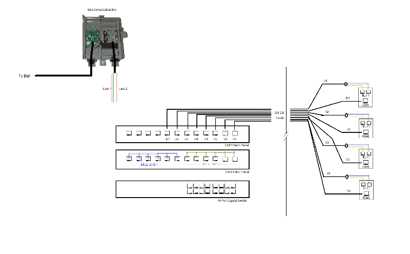
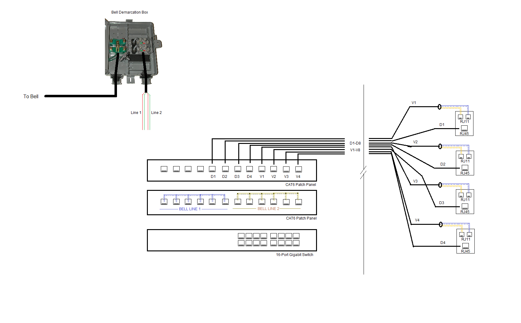
So what I'm planning on doing is running all of the ethernet cables to the patch panel, punching them down in the T568A format. Treat them all the same as if they were all going to be data ports.
Then, I'll daisy-chain the blue/bluewhite pair for 6x of the ports together in parallel, and those ports will be for a single Bell line. I'll do this four times, for each line (24 different ports).
Check the image below. This is my plan so far and you can see how the wall plates have been wired:
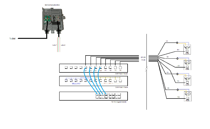
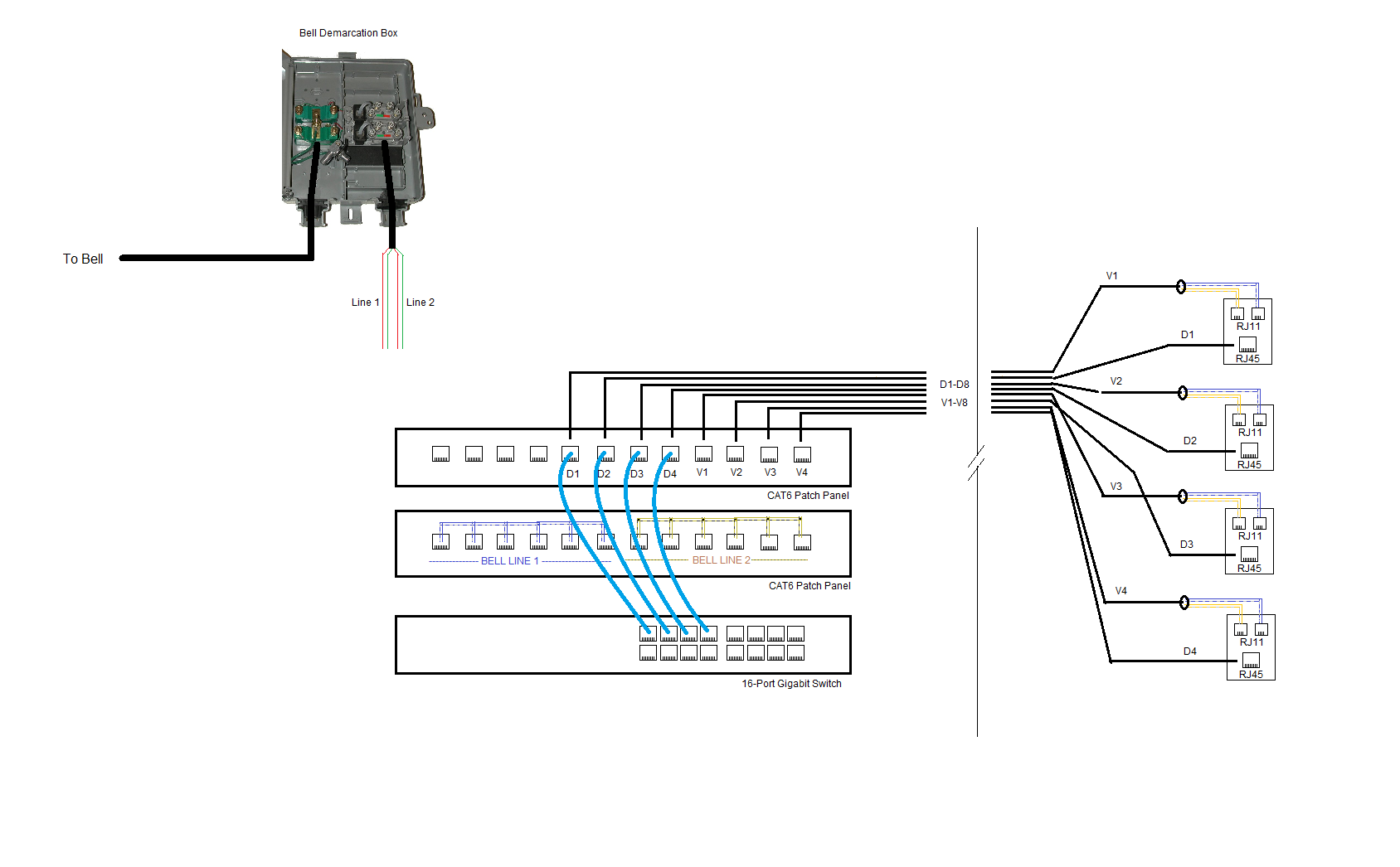
Now it is fairly straightforward how to wire the DATA portion (The D1-D4 ports). I'll get regular straight-through CAT6 patch leads, and connect them to the switch like so:
My question is... what's the best way to wire up the VOICE ports?
The problem is that the V1-V4 ports have upwards of four pairs, each one is it's own Bell line.
I had two ideas:
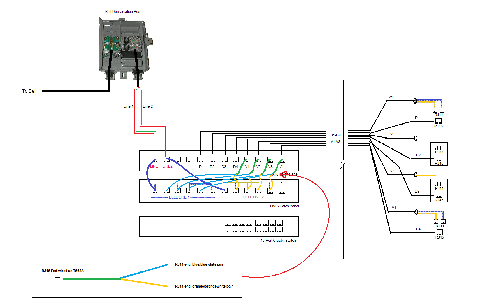
1) I could hack a patch leads, where I cut the end off a patch lead, and wire each twisted pair with it's own RJ11 head, plugging it into the appropriate telephone jack. E.g.:
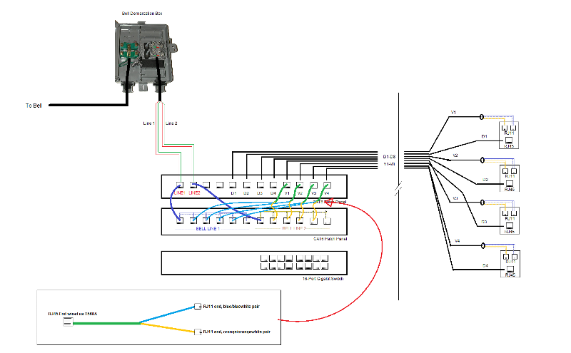
GOOD - it is very clear exactly how everything is wired.
BAD - Hacking the patch leads together and stripping large amounts of patch cable is messy, and unprofessional looking
The other idea I had was this
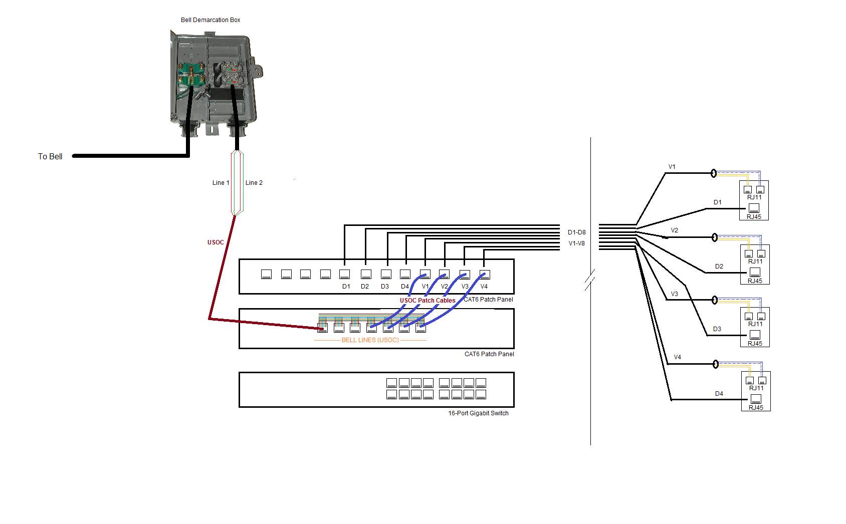
2) Wire the Bell lines on the patch panel to be in USOC wiring standard (see here: https://en.wikipedia.org/wiki/Category_5_cable), and daisy chain ALL 8 wires together.
Then, make special patch cables with T568A on one end, and USOC on the other, and connect one end to the V1 port on the patch panel, and the other to my slab of Bell line ports. One of the Bell line ports would be connected to the actual Bell line on the demarcation box.
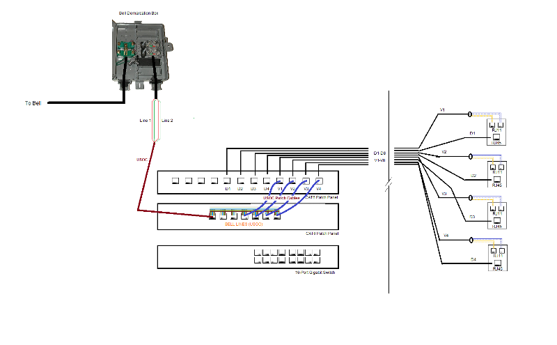
GOOD - Less stripped bare wires floating around
BAD - I STILL need to fashion custom patch cables, and it is confusing to an outsider that I'm using two different wiring standards (T568A and USOC) at the same time.
Neither of these seem like a perfect solution.... I'd be interested in seeing what you guys think I should do.
In total they have around 28 Cat5e wires running throughout the house. Most rooms have 2x Cat5e cables running to the outlet box - one for data, one for voice.
They have four bell telephone lines which they want wired up and easily accessible. Right now, though, only two of those lines are active.
They have already terminated and labelled all of the wall sockets, and they TRIED to wire the patch panel, but it has turned into a big spaghetti mess and needs to be re-done. That's where I'm coming in. They seem quite comfortable wiring up the wall sockets, but they're scared of the patch panel.
The ground rules I've been given:
1) They want the wall plates to remain terminated as they are, 1x wire for the data port, and the other wire terminated in two to four RJ11 telephone ports, each one gets one pair of wires.
2) The patch panel must be wired such that they can easily turn a Voice wire into a Data wire, without having to touch my work in the patch panel. They'd just put an RJ45 keystone jack into the appropriate wall plate and terminate accordingly.
3) All of the data ports and telephone ports in the house must all be active, they don't want to have to fuss around with plugging stuff into the patch panel when they decide to plug a computer into a previously unused Data port in a wall.
So what I'm planning on doing is running all of the ethernet cables to the patch panel, punching them down in the T568A format. Treat them all the same as if they were all going to be data ports.
Then, I'll daisy-chain the blue/bluewhite pair for 6x of the ports together in parallel, and those ports will be for a single Bell line. I'll do this four times, for each line (24 different ports).
Check the image below. This is my plan so far and you can see how the wall plates have been wired:
Now it is fairly straightforward how to wire the DATA portion (The D1-D4 ports). I'll get regular straight-through CAT6 patch leads, and connect them to the switch like so:
My question is... what's the best way to wire up the VOICE ports?
The problem is that the V1-V4 ports have upwards of four pairs, each one is it's own Bell line.
I had two ideas:
1) I could hack a patch leads, where I cut the end off a patch lead, and wire each twisted pair with it's own RJ11 head, plugging it into the appropriate telephone jack. E.g.:
GOOD - it is very clear exactly how everything is wired.
BAD - Hacking the patch leads together and stripping large amounts of patch cable is messy, and unprofessional looking
The other idea I had was this
2) Wire the Bell lines on the patch panel to be in USOC wiring standard (see here: https://en.wikipedia.org/wiki/Category_5_cable), and daisy chain ALL 8 wires together.
Then, make special patch cables with T568A on one end, and USOC on the other, and connect one end to the V1 port on the patch panel, and the other to my slab of Bell line ports. One of the Bell line ports would be connected to the actual Bell line on the demarcation box.
GOOD - Less stripped bare wires floating around
BAD - I STILL need to fashion custom patch cables, and it is confusing to an outsider that I'm using two different wiring standards (T568A and USOC) at the same time.
Neither of these seem like a perfect solution.... I'd be interested in seeing what you guys think I should do.
ASKER CERTIFIED SOLUTION
membership
This solution is only available to members.
To access this solution, you must be a member of Experts Exchange.
SOLUTION
membership
This solution is only available to members.
To access this solution, you must be a member of Experts Exchange.
ASKER
Yup, Dave, you were right. I've just finished the wiring project and indeed there's no reason to have to splice any special cables.
As JRSCGI said, the patch panel is there to keep the wires organized. I could plug directly into the switch, but it is a lot tidier to connect everything to the patch panel, and then patch from the panel to the switch.
As JRSCGI said, the patch panel is there to keep the wires organized. I could plug directly into the switch, but it is a lot tidier to connect everything to the patch panel, and then patch from the panel to the switch.
Glad you got it finished. Thanks for the points.
ASKER
The only place where I have to start hacking together cables is for the one cable that goes to the Bell demarcation box, where I'd screw the various twisted pairs onto the posts for the desired bell lines.
GOOD - consistent wiring standard throughout, voice ports can easily become data ports by moving the wiring and re-terminating the wall box
BAD - Difficult to customize which lines go to which wall boxes, all the pairs are the same and cannot be changed without splicing patch cables together.