

Browse All Articles > SAN 101 Basics of administrating a SAN.
IBM Storage and Cisco Fabric SAN 101
By Neil ChakrabartyMy class notes from the class taught by David Lawrence of IBM on 30 April to May 2, 2007 and supplemented by screenshots of the software systems used.
Disclaimer
This information is provided as the understanding of a neophyte student of storage administration. No warrantee of accuracy or correctness is expressed or implied by this document.
Overview of class context, applicability and topics:
This class was presented to the System Administrators of West Virginia Department of Environmental Protection (WVDEP) and storage administrators from the West Virginia Office of Technology. The WVDEP organization had recently lost their Storage Administrator and so the class was convened to educate the remaining IT staff in WVDEP maintaining and managing the Storage system and Storage Area Network.
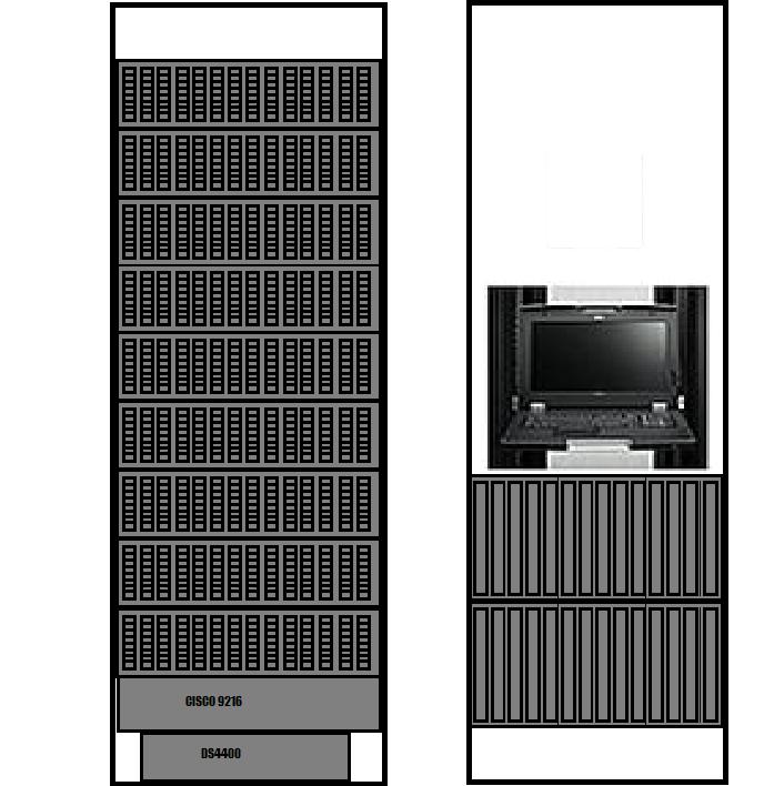
The WVDEP head quarter’s site has an installed IBM DS4400 Mid Range Storage Subsystem with 9 Drive expansion units and a Cisco 9216 fabric switch along with two IBM blade centers with Q-Logic fabric switches internally mounted.
The software used is a combination of Cisco’s Fabric Manager and IBM’s Storage Manager. Therefore this information is relevant to any system using these two softwares and even to other vendors of storage area networks and storage systems as the concepts will remain valid even if the actual software is different.
 Fiber tape and SANS
Tape and Disk paths should be separate because Disk and Tape accesses are different. So do not plug Fiber Channel Tape Drives into the same SAN switch as your Storage Area Network with Servers accessing Disks.
Disk are random access while tapes are streaming oriented. Tapes have high performance when data is sent at the correct speed and uninterrupted. However if there is a hesitation in the dataflow then the tape has to retract with an associated overshoot and then realign to resume writing data.
Shoe shining is a term used to describe the repeated action of retracting and realigning.
Typically a cache drive is used to cache data to tape systems to avoid Shoe Shining
History, Terminology and Concepts:
The goal of the storage area network and storage equipment is to present blocks to an Operating System (OS) just as traditional disk drives do.
SCSI, SP and FP
SCSI Small Computer System Interface and SP or SCSI Protocol was used originally for storage systems. Also RAID levels 1 for mirroring, 0 for striping and 5 for striping with an extra drive for check sum.
 SCSCI used parallel cables, which acted like a large capacitor. As the frequency of data transmission increased so would the reactance, which restricted the length of SCSI cables, and also the number of drives that could be connected since the cables needed to be short.
Later newer versions of SCSI became serial to eliminate this length restriction and allow the connection of more drives using SCSI and SP.
 Fiber Channel Protocol FP was developed from SP.
Central Point, Very Important to understanding the system
Both SP and FP protocols were designed for Single Initiators. That is there would be a single computer on the SCSI bus that would initiate communication with the hard drives.
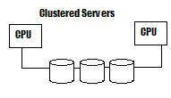
In the case of a clustered server using SP there would be two or more initiators or two or more servers on the SCSI bus that would negotiate for communication to the drives. This resulted in a performance hit.
In addition to clustered negation performance hits there is also the performance hit of just managing the drives and the raid levels for the servers. This load increases as the number of drives and SCSI busses increase
Storage Subsystem
The storage subsystem introduces specialized processors to reduce the load on the servers by managing the disks on multiple SCSI busses.
But this results in more trouble as the hosts communicate and have to negotiate with the specialized processor for connection to the Storage Subsystem.
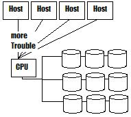 However the processor load for maintaining the RAID arrays is successfully moved from the Host servers to this specialized processor/ controller designed for the purpose.
Storage Area Network
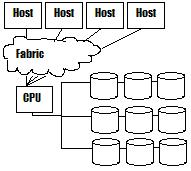
To solve this trouble of multiple initiators and the resulting negotiations for communication we introduce a network switch. As soon as a fiber channel switch is included then we term the system a Storage Area Network. The network we term a Fabric since it is a Fiber Channel Network with FP protocols as opposed to typical LAN or WAN networks.
Zones are analogous to Firewalls in LAN/Wan networks in that they are rules in Fiber Channel switch that control which hosts can see which other hosts and storage subsystems.
 Zones are used to preserve the single initiator system that the FP was designed for, except for the case of clustered servers. In the case of clustered servers then we limit communication to just the servers in the cluster and the storage subsystem so that the communication negotiation is no worse than it was before we added all the other hosts.
Redundancy and Storage Area Networks
In order to have some redundancy in this increasingly vital storage system we put in a second SAN Switch and divide the fabric up into two fabrics an A and a B fabric.
 In this way if any fiber channel lines, host adaptors or switches fail then the system will continue to operate.
In this design then each host has two connections one to the A switch and one to the B switch to form the A and B Fabrics.
The Storage subsystem controller has two connections for the A and B fabrics as well. The storage subsystem processor is also designed to have two internal sets of processors and connections to the drives.
This ensures that there is enough connections for a failure of either the A or B fabric and that each fabric is independent of the other.
Multi-path Drivers
Now the hosts each have an A and B fiber channel connection to A and B switches and A and B controllers this results in multiple paths to communicate with the drives in the storage subsystem thought the fabric. While this is better for redundancy it tends to confuse host servers that expect a single path to a local drive. To solve this problem then we use a multi-path driver on the host to recognize that a single “drive” from the SAN may have multiple paths.
Types of Multi-path drivers:
You should only use one type of multi-path driver per host. That is use IBM’s RDAC or Q-Logic or Novell’s driver but not more than one per server. The drivers would interfere with each other.
Installing OS’s in Hosts connected to the SAN for Boot
The multi-path driver cannot be installed until the OS is installed first. During the initial install for a host OS that is to boot from the San then the zone is set for a single path. That is either Fabric A or B only and not both fabrics. If you fail to do so then the multiple paths will confuse the OS install of most operating systems. The OS will see a single drive as two or more drives and attempt to write to multiple drive and be confused when the other drives also change.
Zoning a single path solves this confusion so that the OS can be successfully installed. Then a Multi-Path driver can be installed and the host re-zoned to allow a connection to both Fabric A and Fabric B.
Some definitions:
LUN - A LUN is virtual disk drive presented to the host from the storage sub system. It is a section of storage from an array defined on the storage subsystem.
Array -An Array is a set of physical hard drives with RAID in the storage subsystem.
Fabric -One switch and its connections.
ISL - Inter-switch link to combine fabrics or switches
SVC - Storage Virtualization Controller
IBM DS4000 - Series Storage Systems
Made by Ingenio, these storage systems are similar in many ways.
In the DS4400 there are two sets of fiber channel modules on the back that are interchangeable. The Left side connects to the switches and hosts. The Right side connects to the drive shelves in an Arbitrated Loop.
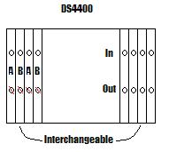 On the Left side only one connection per module can connect to a switch. If you were not using switches then you can connect hosts to these ports and use both ports on the module.
Arbitrated Loop
The arbitrated loop is a Fiber Channel protocol based on 147-device id’s, which limits the number of devices on the loop. The communication is similar to token ring in that a token is passed between the devices to allow communication by taking turns and communicating at a data rate of a Nominal 2Gb which is actually 1.7 Gbit/s or 212.5 MB/s.
Arbitrated loops are fast but break the loop and it stops. Therefore we have a redundant loop.
The IBM DS4400 has four connections to the Fabric 2 A connections and 2 B connections to ensure redundant connection to both the A and B Fabric’s.
Data Rates
Data rates of fiber channel cables set a ceiling for communication speed of an individual system. The actual throughput for a host system is dependant on many variables including drive speeds, other host requests and other issues.
Acronyms:
FLOGIN - Fiber channel login
FCID - Fiber channel ID translates to two sides of a loop.
FCHUB - Fiber channel HUB.
FCAL-loop - Fiber Channel loop
EXP700 and EXP710’s
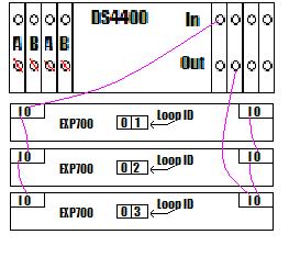
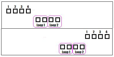
The Drive shelves are connected to the DS4400 by Fiber Channel Loops as shown below
Notice that the cables from the In port go one way across the EXP700’s and the out port goes the other way. This is so that if one of the Fiber channel connectors on the EXP710’s were to fail then communication would not stop.
 Failure mode example
If the line between the In port on the left side of the EXP700 with loop ID 02 and the Out port on EXP700 with loop id 03 were to fail then that loop would only communicate from the DS4400 to EXP700 with Loop ID 01 and Loop ID 02.
However the second loop would still have communication to all three EXP700’s and the DS4400.
The EXP810’s are different, amongst the differences they have a software settable ID instead of the thumb wheel selector like the EXP700 and EXP710’s.
Speed: It is rare to saturate the 2GB link other parameters are more important.
Redundancy: Both the A and B storage controllers have access to all the drives in each shelf.
SFP a.k.a. GBIC Small Form Factor Pluggable or Gigabyte Connector are the devices that plug into each Fiber Channel port for the Fiber cables to connect to. They convert the optical signal into electrical signals.
Performance and Redundancy with Array and Lun Assignment Best Practice:
For example with 5 shelves spread the Arrays with 1 drive per shelf, so that you can loose a shelf without losing data. Even with Two drives of an array in a Shelf you would loose the array if you lost the shelf.
The case against large arrays:
Big arrays have problems with performance when drives fail. When a drive fails or is about to fail the system will copy data to a Hot Spare drive. The operation to fill a hot spare is resource intensive and proportional to the size of the array. Larger arrays have larger overhead to re-shuffle the array, which increases drive contention on the SCSI busses inside the Drive Shelves. Also the increased activity exercises the drives more reducing drive life.
The sweet spot is 8 to 10 drives.
What to do instead of large arrays:
If you have a host server that needs more space than can be arranged with an array of 8 to 10 drives simply create more than one array. Create Luns on one or more arrays and assign them to the host server. Most server OS’s can create a RAID 0 between multiple Luns. Use this software raid feature to stripe across the two or more Luns. The net result is that the arrays will be smaller and faster to recover from drive failures and the arrays will be tolerant of shelf failures. OS’s do not experience very much overhead with RAID 0 so while you are shifting some of the workload from the Controller to your host OS this extra work load is well worth the increase in reliability and performance.
How to change large arrays to a set of smaller arrays
Create new arrays and copy the data over then delete the old array.
Why have a SAN?
The reasons for a SAN are it’s flexible and dynamic. You can provision a Lun on a whim. Conversely SCSI is not so easy to manage.
Assignment of Hosts to Arrays Best Practice:
Mix your busy systems with less busy systems. Do not put all your busy systems together on one array it will simply lead to performance problems. Better to identify what systems are busy when and spread the load over the arrays that you have. For example a production system used during the day can be mixed with servers that do night batch processing since while both are busy they are busy at different times.
The challenge:
The main concern for performance in a storage system is spindle or drive contention. This should be your main consideration for how systems and arrays are designed to reduce drive contention.
Understanding a common Performance Problem
The AIX operating system from IBM sends data to a SAN just as fast as it can without waiting for feedback from the SAN saying it’s written.
The Windows Operating systems send data to the SAN and wait for confirmation of a write.
This means that Windows will spend more time waiting.
To adjust the san to perform better for windows you may consider increasing the striping on the san by reducing the Luns sizes and creating more Luns over more drives. That is assigning smaller Luns in different arrays to windows and have windows stripe (RAID 0) across them. That way windows will be able to do more work faster as the overall wait time will be reduced with more drives, as windows is waiting for one Lun to respond it will continue writing to the other Luns.
Each operating system will have its own characteristics in this area so as you gain experience with the performance tools of each OS you can tell if this problem is present.
Storage Manager
The current version 9.16 is written in Java so that the interface is the same across operating systems.
More info
Lots of great books by IBM
www.ibm.com/redbooks
www.ibm.com/redbooks
Drivers, and Firmware and Bios updates and more
www.ibm.com/support
Finding the drivers and firmware often confuses people so here is how:
System storage
Product Family -> Disk Systems
DS4400
Download
Storage Manager
Firmware
Download the firmware zip files and then unpack them into an empty folder. This will create a directory tree for the firmware.
Read the Readmes for dependency information.
SAN Surfer
Can be downloaded under the tools link. San Surfer can bypass the OS while the host is up and see Fiber Channel HBA information.
Deleting a Lun and Array Defragmenter
When you delete a Lun from an array the Storage Manager does not combine the free space automatically. To combine the free space you can use the Array Defragmenter option in the Storage Manager. The Array Defragmenter is unfortunately named in that people confuse this with the Windows Drive Defragmenter. There is a big difference between the two defragmenters. Windows Drive Defragmenter is used periodically to increase drive performance by changing the layout of data on the drive. The Array Defragmenter only combines unallocated free space and does nothing to improve performance.
It is a mistake to run the Defragmenter for any other purpose than to combine unallocated free space as the operation of Array Defragmentation exercises the drives in the array and creates a performance hit while operating.
Creating an Array
Click on the Create new logical drives and arrays icon in the top left of the Storage Subsystem toolbar.
This brings up the intro window below.
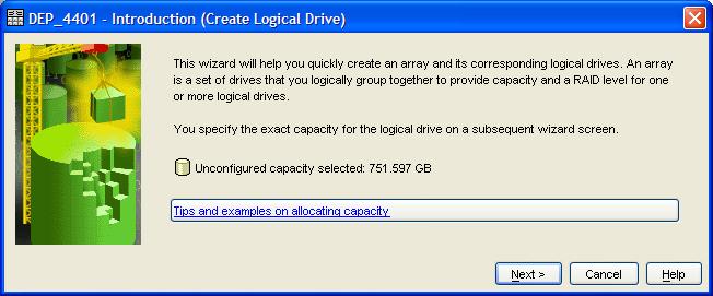 Then click Next
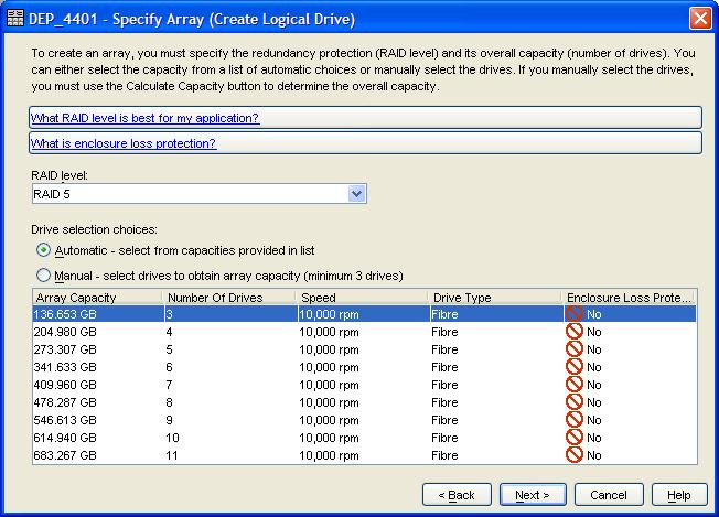 Choose the RAID Level
Use either automatic or manual drives selection.
Automatic is fine but Manual allows you to choose which drives to use.
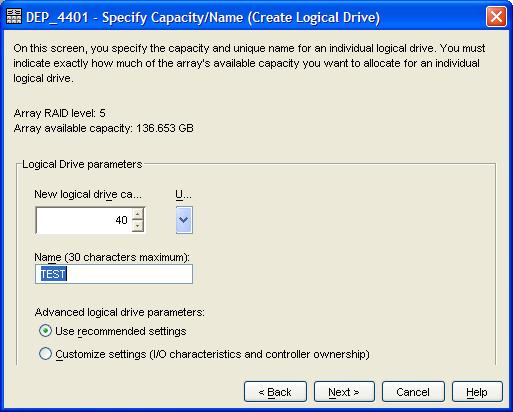 Then set the size and name of the first Lun to create in the Array.
Under the customized settings you can effect read a head buffers and set controllers but just use the recommended settings.
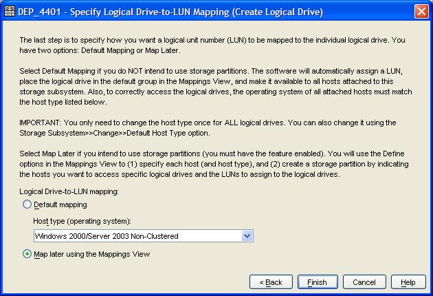
 Next you select the Host OS Type.
There are many host types to choose from. By the way LINUXCL stands for Linux Cluster.
Clicking Finish creates the array and the Lun.
 LUN Parameters
By right clicking on a Lun in the Storage subsystem menu you can change the parameters of the Lun. When a new Lun is created the wizard stops after the commands have been issued to create the Lun but before the Lun has finished being created. You can see the clock icon over the Lun as creation is completing.
One option you can change is the modification priority, which on our system defaults to a high priority. By right clicking on the Lun and choosing change modification priority you can set the priority down to prevent performance issues with your other systems on the same array.
Another option that can be changed is the Segment Size of the Lun. Performance can be increased for some host systems by setting the segment size. For example Oracle block sizes should match the Segment size.
You can choose to increase a Lun size which depending on the OS may or may not require a reboot to recognize. Most operating systems will not resize its partitions even if it recognizes the extra space assigned.
Warning: Array Clock icon
Minimize disturbances to arrays during rebuild operations such as creating arrays or immediately after a drive failure. Normal host access is ok but don’t pull bad drives or create or delete Luns. Or other changes from storage manager.
Volume Copy
This is an optional feature of the Storage Manager system. First create a Lun to copy to. Then use volume copy to copy one Lun to another Lun.
You should then set your host system to quiess writes to the Lun to be copied or Write Suspended mode. Read operations are ok.
Next sectors are copied from one Lun to the destination Lun. If a write happens then the write is done and the sector is copied again before the acknowledgement is sent. Bit maps are maintained to track which sectors have been copied to keep track of what needs to be update to keep up with reads and writes.
Volume Copy works at the default modification priority unless you change it after it starts.
Flash Copy / Snapshot
This simulates a point in time copy. The goal is to make a copy of a Lun instantly as if at one particular moment in time. This is simulated by creating a copy area associated with the Lun at about 15 to 20% of the size of the Lun to simulate a copy for. Though pointer manipulation new writes are redirected to this new copy area Lun. Reads are also redirected to a combination of data on the original Lun and the Copy area Lun to show the correct data with changes. Also the old data remains on the original drive ready to copy if desired.
DROC - Data Rate of Change generally is 3 to 5% for most hosts.
WROC - Write Rate of Change generally 5 to 8% for most hosts.
Profiles:
Storage Manager has a profile feature, which shows every setting in the system. It has tabs to show subsets and can export to a text file.
WWN, World Wide Port Name - A number represented in Hexadecimal sets of two digits separated by colons used to identify ports and hosts in a fiber channel network. For example b4:61:62
Nodes have WWN’s and so do the ports. Some hard ware vendors keep the node name constant across all ports of the node while others do not. The IBM DS4400 has a consistent Host WWN.
Storage Networking Industry Association (SNIA) - http://www.snia.org/home
Switches:
It’s best not to mix switch vendors in side the same SAN. However, we did we have Q-logic and Cisco switches. The result of mixing switches is incomplete communication in setups. Our mix works for the most part but some settings are not replicated from our Cisco switch to our Q-logic switches. This works well enough for us that we don’t worry about it. Other combinations may not be so lucky as zoning and other problems could result.
Storage manager
Storage manager - Subsystem menu
Save Configuration option
This option is generally not useful. You do not want to restore from this saved configuration. However it is useful to setup a duplicate system at a Disaster Recovery Site.
How to enable a premium feature:
Ask your sales agent for a key number. Enter the Key number into storage manager and a file is generated. Upload the file to IBM and then download another file and then load that file into Storage manager.
Change sub-menu
Enclosure order- allows you to change the display order to reflect your physical setup.
Cache- Don’t make changes unless in communication with IBM support. Better to change this on the Logical Drive menu at the LUN level.
Media Scan - Detects sectors about to fail. Leave this alone unless you have problems then you can increase the scan rate.
Failover Alert Delay - Effects email generated by the system.
Set controller clocks Self-explanatory.
Storage manager - View menu
Task Assistant- Not used.
Mappings - Changes to the mapping tab.
Associated Components - When a physical component is selected this option displays a list of other components that are associated.
Find- Searches for a Lun name.
Storage manager -Array Menu
Locate an Array - make the lights blink
Change an Array Raid Level - performs this operation online may need more drives reduces performance during the operation.
Storage manager - Logical Drive (LUN) menu
Cache Settings-
If the Host does not utilize the Cache then disable it per Lun.
If the Host uses all the Cache then increase the Cache size.
Write Cache in mirrored and good for 24 hours without power. After 24 hours of power loss you will have corrupted data.
To clear the cache restore power and shutdown.
Tune the cache settings by making small changes and observing the change. For example change by 100 or 200.
Media Scan setting - Per LUN
Flash Copy- Snapshot a LUN
Storage Manager - Controller Menu
Loop ID- Don’t change.
IP Addresses - There are two tabs, one for controller A and one for controller B. The addresses should differ by 1. Changing the IP’s will cause the GUI to lose connection.
Storage Manager - Drive Menu
Assign Hot spares- manual control of this is better. You should have no less than 2 hot spares and more if you can.
Storage Manager - Advanced Menu
Maintenance Download -
Controller Firmware
Can load changes and not activate them
Can later activate or clear changes
Can load changes and not activate them
Can later activate or clear changes
NVSRAM
ESM Firmware (Shelves like EXP700, EXP710)
Drive Firmware
Drives cannot be updated on line.
Stop all IO to the drives
Can pick out individual drives
Drives install in parallel
Drives cannot be updated on line.
Stop all IO to the drives
Can pick out individual drives
Drives install in parallel
Persistent Reservations - not relevant
Place Array - On or Off line.
Troubleshooting
Capture state info - Useful
Run diagnostics - Leave alone
Capture state info - Useful
Run diagnostics - Leave alone
Recovery
Initialize - Clear the array.
Revive - Try to revive a drive, better to replace a drive. Do not use while rebuilding an array (Clock Icon)
Reset - Wipe San (lose all data)
Place- A controller on or off line
Enable Controller data Transfer - Catch up a controller that was off line.
Redistribute logical drives - no comment
Defragment Array - Consolidates unallocated free space, consumes overhead does not increase performance.
Check array redundancy checks
Performance monitor
Can be found in the storage manager subsystem menu. This is where you check for high or low cache hits to adjust cache sizes in the Logical Drive menu.
Columns
Current IO / Second and Max IO / Second - useful numbers
Performance tuning is a Black Art as there is not much information so it’s a matter of experience and intuition.
Looking a drive light flashing rates and patterns is useful.
TPC - IBM’s Total Productivity Center http://www-03.ibm.com/systems/storage/software/center/index.html can give better historical data to base performance tuning strategies.
Also you can write you own screen scraping software to gather the information by starting / stopping reading and repeat of the performance monitor data.
The Write column is missing but is simply 100 the Read %
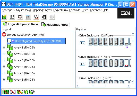
Storage Manager Mapping View
Consider the first view as a view of the shelves from the point of view of the DS4400 or Storage controller. Then you can think of the Mappings view as the view from the DS4400 or Storage controller looking at the hosts. The mappings view shows the Luns and their connections to hosts.
The first entry Undefined Mappings shows the Luns that are not mapped to hosts.
To define a new host
Right Click on the Storage Subsystem and choose Define Host Group.
Enter the name for the new host group then you can add hosts by identifying the host using HBA ID (MAC) or an Alias Name. You also identify the host type. Once the host is added you can move the host to another group or delete or rename the host.
 Clustered hosts
If you assign a Lun to a host group and two or more hosts to the host group without a clustered file system then you will lose the data on the LUN. That is Operating systems will over write the Lun as both hosts will consider the Lun to be their local drive and not realize it’s shared. Clustered file systems are needed to properly share drives in this manner.
The proper way to setup a cluster is to bring up one host setup the drive start the cluster software on the second host and change the host assignment. Better to change the host assignment then the host group.
Adding More Storage and upgrading from EXP700 to EXP710’s
Upgrade the EXP700 to EXP710’s
1.) Get the system in to a total green state with no errors.
2.) Shut down the hosts
3.) Set the controllers to preferred paths or set the preferred path to the actual path.
4.) Upgrade the EXP700’s
5.) Check the drive enclosure ID’s to insure they are correct and unique.
6.) Bring the system back up.
Add the new storage units.
1.) Plan for 8 shelves in one loop. There are two loops.
2.) Shut system down
3.) Add storage to correct loops
4.) Check drive enclosure id’s to insure they are correct and unique.
5.) Bring the system up.
Remote Mirroring and Disaster Recovery
IBM’s Remote copy feature and EMC’s SRDF/A systems mirror data to remote SANs.
One scenario is for each write to a local SAN also write to the remote SAN and wait for a response to finish the write. If this happens at the speed of light then over a distance of 100Km there would be a .6 millisecond delay for each trip. A total of 1.2 milliseconds for a round trip along with a .8-millisecond delay for overhead for a total time of 2 milliseconds additional time in the transaction.
Alternately we write and not wait for the acknowledgement but if the link were lost then we might loose write order integrity. IP communication does not guarantee delivery it is a best effort protocol. TCP/IP has no guarantee of order of delivery. Therefore buffers would be needed at both ends to re-sequence the writes into the correct order.
Power fail consistency is a goal, so there would need to be a write suspend mode to wait and update when the correct buffers arrive.
High performance
How to get the most performance for your critical systems?
Use the outer most 10% of a large number of drives. This will reduce latency. Use the other 90% of the drive for non-simultaneous use such as for backups.
A good bookMark Farley Building Storage Area Networks
Storage Area NetworksTechnically the SAN is the network for accessing Storage and not the storage its self. It is common usage to refer to the entire system as a SAN. However in the IBM support site Disk systems are treated separately from Switches where the Switches are identified as SAN components and the Disk systems are separate.
Project description
We have identified numerous areas in which our SAN can be improved. Therefore we are going to rebuild our zone sets using single initiator zoning and naming conventions. Our system is a production system so we will setup this new zoning scheme without disruption of the existing systems until we use a scheduled down time to switch the system over to the new zoning scheme. We will be using the CISCO 9216 managed using Fabric Manager and the Q-Logic switches in Blade Center.
Switches
Fiber channel Switches are generally comprised of sets of 4-fiber channel ports called Quads. Quads have an ASIC (application-specific integrated circuit) chipset associated with them internally inside the fiber channel switch. Various vendors create chip sets for quads. This accounts for the fiber channel switches containing multiples of 4 ports since the base unit of ports is a quad.
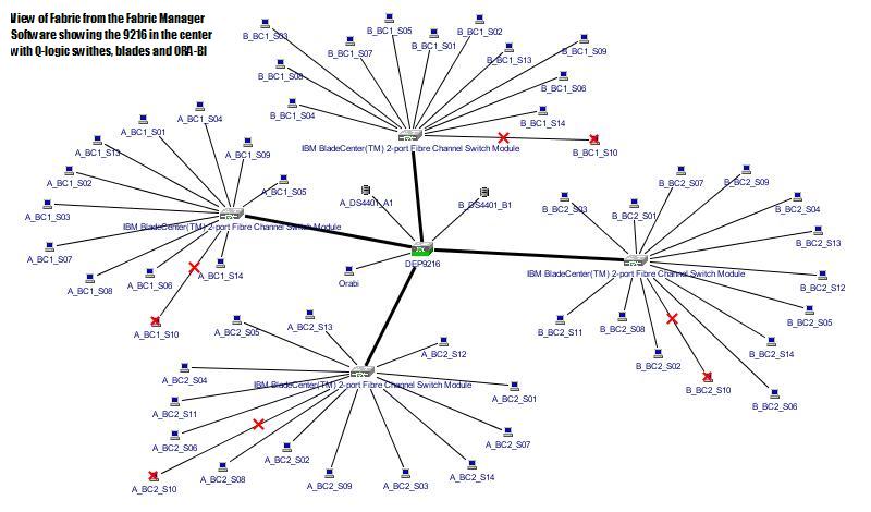
In our environment we have 5, 16 port fiber channel switches. Two are inside each of two blade centers and are the Q-Logic switches. The last switch is the 16 port Cisco 9216 switch.
Q-Logic switches
Inside each blade center is two sixteen-port Q-Logic switches. Each Q-Logic switch has one connection to each of the 14 blades and two connections to the rest of the FABRIC. Inside the blade center then we associate one switch to the A fabric and the other switch to the B fabric.
The lower switch is IO module 3 so we term it IO3 or BC1_IO3. Since we assign this switch to the A fabric we name it A_BC1_IO3. We also name each of its 2 ports for the fabric as A_BC1_IO3_P1 and A_BC1_IO3_P2. Similarly for the second blade center we have A_BC2_IO3_P1 and A_BC2_IO3_P2.
CISCO Switch and V-SAN
The CISCO switch has a feature called V-SAN. This feature causes the CISCO switch to act as though it were more than one switch by creating virtual switches hence virtual SANS, since the definition of a san is a fiber switch.
The Default VSAN 0001 is not supposed to be assigned to ports and is meant for overall management of the CISCO switch.
Naming Convention
Logical naming conventions are useful for keeping track of the many deices in a Storage Area Network. For our class we will setup the Storage Area network using the following naming convention.
A_BC1_S01
1.) Which FABRIC A or B
2.) Which Blade Center BC1 or BC2.
3.) Which Slot in the blade center S01 though S14
WWN and Blade identification
Each blade has 2 WWN per HBA one for the HBA and one for the Q-logic switch port in the blade center. By connection via Telnet to the Q-Logic switches we can query the port information and determine the WWN’s of the ports. By knowing which port connects to which side of the Storage controller we know which Q-Logic swiches are A and which ones are B fabric.
B_BC1_Qlogic_IO_4: admin> show port 1

                        Port Number: 1
                        ------------
                        AdminState       Online              PortID           660100
                        AsicNumber       0                   PortWWN          20:01:00:c0:dd:01:d8:02
                        AsicPort         1                   RunningType      F
                        ConfigType       F                   SFPPartNumber
                        DiagStatus       Passed              SFPRevision
                        EpConnState      None                SFPType          NotApplicable
                        EpIsoReason      NotApplicable       SFPVendor
                        LinkSpeed        2Gb/s               SFPVendorID
                        LinkState        Active              SymbolicName     Port1
                        LoginStatus      LoggedIn            SyncStatus       SyncAcquired
MaxCredit 12 XmitterEnabled True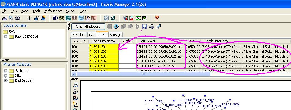 Set the Enclosure names for the blades
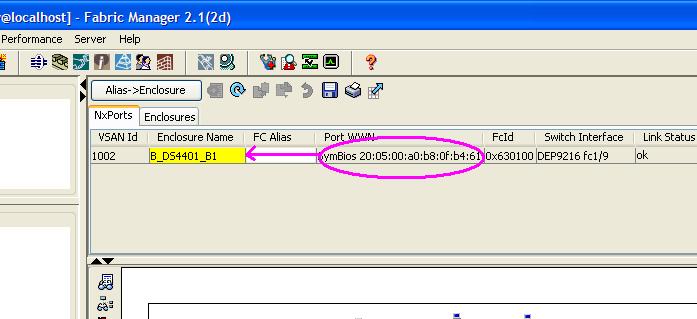
Using the Cisco Fabric manager we set the enclosure names for each blade, using the hosts tab of the main display.
The switch interface column identifies the blade so that we can easily fill in our names into the closure name field. With that and knowing the Port WWN’s we can fill in the Enclosure names using out naming convention.
Set the controllers Enclosure names
We set the controller frame names using the right click menu when right clicking on the controller in the map view and choosing device attributes. Knowing the WWN of the A and B fabric.
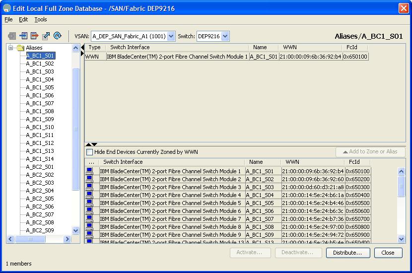
 Next create Aliases in the Zone database for all the blades.
We do this without associating the WWN’s at first to save time. In fabric manager we choose the Zone menu and select Edit Local Zone Database. Select the alias folder in the tree view presented and use the right click menu to insert aliases.
Next we associate the blades to the aliases by adding the WWN using the enclosure name we entered earlier to identify the blades. We can either drag from the lower pane or use the add button.
Create aliases for the controller ports and hosts not in blade centers.
We create an alias for the A and B ports in the controller and for the ORA-BI server which is the one external host in the storage network. These names are A_DS4401_A1 and B_DS4401_B1 and ORA_BI.
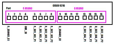 New V-SANs and Fiber channel connections
When defining a V-San we must associate the new V-San with ports on the CISCO 9216. We will allocate some unused ports to build the new zones and then re connect the fiber connections and re associate the zones during the down time scheduled.
This is the new connection scheme we plan to implement.
So we create the New V-SAN using the new V-SAN button in the toolbar in Fabric manager. We assign create the two new V-SAN with the names A_DEP_SAN_Fabric_A1 and B_DEP_SAN_Fabric_B1 and assign them to unused ports on the 9216.
Then we use device manager to start the ports.
Then we edit the Local Zone Database and Copy the two new V-SANs so that all the zone information exists in both V-SANS.
 ZONE SETS
Zone set represent a file with configuration in it that describes the defined set of zones. Only one zone set can be active at a time. To make a change copy the active zone set make your change. Then activate the new zone set. This way if you make an error you can revert back to the previous zone set.
Debugging the Fabric
Whenever there is doubt about the fabric such as a host fails to report. Here are some steps to verify:
1.) The HBA is turned on in its BIOS settings.
2.) The Alias’s are correct.
3.) The Frame name is correct.
Note verify the above with the WWN for the HBAs and r the MAC addresses.
Create a zone set and zones.
We create single initiator zones, meaning one zone for each HBA in the hosts. This most closely simulates the environment of a simple SCSCI bus where only one host exists on the bus. Each zone we create will contain an HBA and a port on the controller. This way the HBA can only see one of the controllers and no other hosts. Even the Clustered servers are configured this way. The clustering access is taken care of in the Mappings view in the Storage manager.
Moving to a new Controller
Drives in the san have a DAC store on each disk that contains a configuration identifying the owning controller. When switching a single drive from one san to another the drive negotiates with the other drives and is out numbered so the drive switches to its new environment. If you take a shelf full of drives and move it to another controller then the drives remain convinced by their number and will not connect to the new controller.
So then to move one way is to migrate an array at a time. So when the drives move they are deleted first.
Moving to a new controller is very complex consider hiring a consultant to assist.
Inter Switch Links
A single line between two switches is an Inter Switch Link ISL. Two or more lines is a Trunk. Trunks require separate licenses to be enabled.
FSPF Fiber Shortest Path First
FSPF was developed by Brocade and adopted industry wide. Essentially this is a crude attempt at load balancing where when the connection first starts the system determines the shortest path and then never alters it.
Buffer-to-Buffer Credits
There is latency in the communication from hosts though the Fiber Channel network and to the drive controller and eventually the shelf and drive. To minimize the latency buffering is used to buffer the signals inside of each switch for each port. Buffer to Buffer credits then is a system used to evaluate which hosts benefit the most from larger buffers.
Thus buffer space is taken from hosts that do not take advantage of the buffering and the buffers are given to the hosts that will use them.
Note this is a self-adjusting system do not change it’s setting without having IBM support on the line.
DS4800 as compared to the DS4400
The DS4800 is a newer Storage controller than the DS4400 currently installed in WVDEP. The new controller uses new technology that is much faster, and therefore configured differently. The software the Storage Manager software is the same but the physical system is very different.
The DS4400 has a Front top and bottom that are interchangeable for the A connections and the B connections. The back of the DS440 has plug-ins for fiber hubs. The fiber hubs are interchangeable. However the left side is for host connections and the right side is for drive connections. (See page 6)
The DS4800 has a top and bottom that is also interchangeable but no hub modules. You can take the top half, flip it over and use it as the bottom half.
The host side of the 4800 can connect up to 8 switches while the 4400 can connect to two switches or four hosts.
The drive side of the 4800 has four drive loops while the 4400 have two.
The IOP can get to the 40,000 ranges while on the DS4400 you can get to the 1,500 ranges.
The extra drive loops are good for either more storage or for more types of storage. For example SATA drives can be isolated on a loop as well as other storage types.
 Install a new host and connect to a Lun
Windows Boot to SAN and Boot Lun Assignment
Create a Lun for the boot.
Create the Host Group for the host.
Add the Host to the Host group and its HBA if not already created.
Insure that the HBA is for either Fabric A or Fabric B and set the preferred path to match for a single path.
Install Windows and press the F6 key to install drivers for the SAN.
Use the Q-Logic driver for the HBA for boot from san available on the www.Qlogic.com site. We use the 2300 Q Logic cards at WVDEP.
Windows RDAC install
You can download the RDAC install from www.ibm.com/support storage systems, product family = Disk Systems DS4400, download, firmware & tools, storage manager, RDAC for windows.
Download it and extract then run the large file in the windows subdirectory. Accept the defaults next, next and choose HOST Install.
MPIO Microsoft driver does not work by itself it works in conjunction with the RDAC driver from IBM.
Connect the new host to a lun
In storage manager select the HBA in the storage manager host view create or assign lun to the HBA and reboot the host.
In the host’s device manager you will see the entry for RDAC virtual disk, which represents the connection to either a lun or luns.
SAN Surfer shows the settings of the HBA card while the system is up and running.
To assign a new lun
In Storage manager right click on the lun and add an additional mapping and find the Blade to add. IE; BC1_S09.
SVC Storage Virtualization Controller
This is another specialized computer you can add to your SAN. This SVC computer understands storage so it does not need RDAC or other drivers to understand storage from multiple vendors.
You can assign luns to it in a managed disk group. The SVC can then intern present portions of that assigned luns as new luns to hosts.
The SVC can be connected to multiple types of sans and then present this out to other servers as needed.
The SVC can perform remote mirroring across different SAN vendors in different locations.
Have a question about something in this article? You can receive help directly from the article author. Sign up for a free trial to get started.
Comments (1)
Commented: