Branch office inter-connectivity: A free and industrial VPN approach.


Introduction
In this article, we provide a solution to connect your headquarters building (HQ) to any number of branch offices using industry-grade and free networking operating system and VPN protocols.
Note: (TL;DR)
- The items in Bold help you to skim through the article better.
- The conf, commit and save commands are crucial, I do not repeat them always but do not forget to use them.
Prerequisites
For this scenario we need:
- A Computing node at each location (HQ and Branch).
- Note: It could be physical x86 or virtual machine on ESXi, AWS, and so on
- An internet connection with a Static IP address at HQ.
- An internet connection at each branch.
- Denoted Internal IP ranges used on LAN of each branch and HQ.
- A different range of IP addresses for your VPN tree.
- A copy of our used cloud router at each location (HQ / branch).
Note: In this approach, we will use VyOS as our cloud router and Wireguard as our VPN protocol.
Assumptions
Now let us assume and gather some information to start:
- Your HQ building: the LAN uses 192.168.10.0/24 (internet gateway = 192.168.10.254)
- You have three branches LAN as follows:
- Building-2 LAN using 192.168.20.0/24 (internet gateway = 192.168.20.254)
- Building-3 LAN using 192.168.30.0/24 (internet gateway = 192.168.20.254)
- Building-4 LAN using 192.168.40.0/24 (internet gateway = 192.168.20.254)
- We set aside 192.168.200.0/24 for our VPN routing
- We set aside on LAN-IP and one VPN-IP at each location for our cloud routers:
- HQ Building Router: LAN 192.168.10.200, VPN=192.168.200.10
- Building-2 Router: LAN 192.168.20.200, VPN=192.168.200.20
- Building-3 Router: LAN 192.168.30.200, VPN=192.168.200.30
- Building-4 Router: LAN 192.168.40.200, VPN=192.168.200.40
- You have an internet connection with a static IP 1.2.3.4 at HQ
- You have forwarded (a.k.a destination-NAT) UDP port 12345 to 192.168.10.200 from your internet gateway at HQ.
Obtaining software
At each location grab a copy of VyOS network operating system depending on your platform:
- For ESXi, use the OVA virtual appliance.
- For AWS, use the AMI appliance.
- For physical x86 or other hypervisors, use the latest ISO Image.
Deploying software
At each location deploy an instance of VyOS accordingly:
- For ESXi, deploy OVF / OVA template
- For AWS, instantiate your AMI image
- For physical machines or other deployment types, boot from the ISO or burn and boot from CD/DVD. then issue the install image command and follow the instructions at the live-cd shell after boot. After completion, issue poweroff and remove the CD or unmount /detach the ISO image.
$install image
$poweroffNote: the above is only for an ISO-based installation, the deployment method has already performed this
during deployment of OVA / IMA.
Initial Network Configuration
At each location make sure your VyOS instance has two network interfaces and power both on. Then, at each instance set the IP address for eth1 and eth2 and a default gateway respectively, for example at the HQ issue the following commands:
$ conf
# set interface ethernet eth1 address 192.168.10.200/24
# set interface ethernet eth2 address 192.168.200.10/24
# set protocols static route 0.0.0.0/0 next-hop 192.168.10.254
# commit
# save
# exit
$ Note: by issuing conf, you enter the configuration mode, by issuing commit you apply the changes from memory scratch space to working memory and by issuing save, you save them as the startup-config for later reboots. Finally, by exit, you go out of configuration mode.
Do the similar setup at other buildings with the relevant IPs and gateway addresses, for example at Building-2 use:
$ conf
# set interface ethernet eth1 address 192.168.20.200/24
# set interface ethernet eth2 address 192.168.200.20/24
# set protocols static route 0.0.0.0/0 next-hop 192.168.20.254
# commit
# saveNote: While not in configuration mode, you can ensure your settings by issuing show interfaces command to confirm the name and IP addresses assigned to the interfaces. You may also issue show IP route to ensure the effectiveness of your default gateway. You may even issue ping 8.8.8.8 to confirm an internet connection. If you are in configuration mode, you may issue those command by prefixing them with run such as run show interfaces.
You may prefer now to connect through ssh instead, so enable it by issuing the following command at the console:
$conf
#set service ssh port '22'
#commit
Generating and Transferring required keys
Wireguard protocol requires a pair of keys (private and public) for each connecting node. So at each location configuration mode:
$generate wireguard keypairIf you get some errors at the above step, make sure you have not booted from the Live CD by looking at the output of the following command:
$show versionNow you need the public key of HQ node at all branches as well as the public key of all branches be available at HQ node for further configuration, so print the keys and save a copy via ssh shell into your text editor for further usage:
$show wireguard pubkeyConfiguring central listener at HQ
At HQ we need to enable listening for incoming connection on the UDP endpoint 1.2.3.4:12345. In configuration mode, issue the following commands:
#set interfaces wireguard wg10 address '192.168.200.10/24'
#set interfaces wireguard wg10 port '12345'
#set interfaces wireguard wg10 mtu '1280'Note: You may find changing the MTU size suitable after initial setup for fine-tuning your deployment, hence you have it in the third line above at hand (You can also change Maximum Segment Size of the TCP protocol in conjunction, which is out of the scope of this document, but come back and read from here later).
Allowing each branch to connect
At the HQ router, for each incoming connection, you should create a peer by knowing its public key and allowing at least its tunnel address and one or more or a subnet of addresses at destination LAN in the relevant access list. To do this for example for Branch-2 ,issue the following commands at HQ router:
set interfaces wireguard wg10 peer Branch2 allowed-ips '192.168.200.20/32'
set interfaces wireguard wg10 peer Branch2 allowed-ips '192.168.20.0/24'
set interfaces wireguard wg10 peer Branch2 pubkey 'abcThePublicKeyStringofTheBranch2RouterIsHereXyz='
set interfaces wireguard wg10 peer Branch2 persistent-keepalive '15'Note: Wireguard protocol is designed to be silent while nothing is transferred, but behind a NAT you may need a keep-alive to ensure the UDP mapping is not forgotten by the gateway router and is kept alive respectively.
Configuring connectors at branches
At each branch, you should initiate the connection to 1.2.3.4:12345 and allow at least the tunnel address of the HQ router and a portion or whole of the HQ LAN to travel through the tunnel. You should use the public key of the HQ node that you recorded previously. To configure, issue the following commands:
set interfaces wireguard wg20 peer HQ allowed-ips '192.168.10.0/24'
set interfaces wireguard wg20 peer HQ allowed-ips '192.168.200.10/32'
set interfaces wireguard wg20 peer HQ endpoint '1.2.3.4:12345'
set interfaces wireguard wg20 peer HQ pubkey 'xyzThePublicKeyStringofTheCentralHQServerIsHereAbc='
set interfaces wireguard wg20 peer HQ persistent-keepalive '15'
Configuring routes
Now we need to inform the router at each node to transfer traffic for other nodes to the tunnel address of the HQ. Similarly, at the HQ we need to inform the router to transfer traffic destined for each branch's LAN to the respective peer tunnel address in order to establish routing between Branch-2 and HQ we should do the following:
HQ Router:
set protocols static route 192.168.20.0/24 next-hop 192.168.200.20Branch-2 Router:
set protocols static route 192.168.10.0/24 next-hop 192.168.200.10Inter-Branch Traffic
Optionally, if you want Branch-2, to see Branch-3 as well, add the following route:
set protocols static route 192.168.30.0/24 next-hop 192.168.200.10
And do not forget to allow Branch-3's traffic to travel through the tunnel with HQ by issuing:
set interfaces wireguard wg20 peer HQ allowed-ips '192.168.30.0/24'Testing from LAN clients
At each LAN, the users may browse the internet using their default gateway, for example at HQ, each workstation has a default gateway set to 192.168.10.254. Now we need to set routing information in each client to inform them where to send the traffic destined for Branch-2, Branch-3, etc.
To do this, you may push and distribute the routes from your DHCP server at each LAN (out of the scope of this article), or you may set up a script to add the routes and specify the IP address of VyOS router at each location to handle the traffic of other locations. For example, at workstation-001 located in HQ LAN, the following commands should be run depending on their operating systems:
- On Windows:
route add 192.168.20.0 mask 255.255.255.0 192.168.20.200 metric 1 /pNote: The target computers on Branch-2 LAN should also have the route for reverse path added to them, if not you will only be able to see up to the routers and not the clients, hence add the reverse paths at destination nodes the same way depending on their OS:
- Ubuntu:
up route add -net 192.168.10.0/24 gw 192.168.20.200 dev em1 Testing the results and expectations
Now you should be able to ping 192.168.20.2 (a server at branch-2) from workstation001 at HQ.
Troubleshooting
- View the status of the wireguard tunnel at each node, at HQ for example, and analyze the results:
show interface wireguard wg10 - run ping specifying peer tunnel addresses from each VyOS instance and analyze the results
- run traceroute command from each VyOS instance to destination LAN addresses and analyze the results.
- monitor bandwidth usage with statistics and live ASCII graph:
show interface wireguard wg044 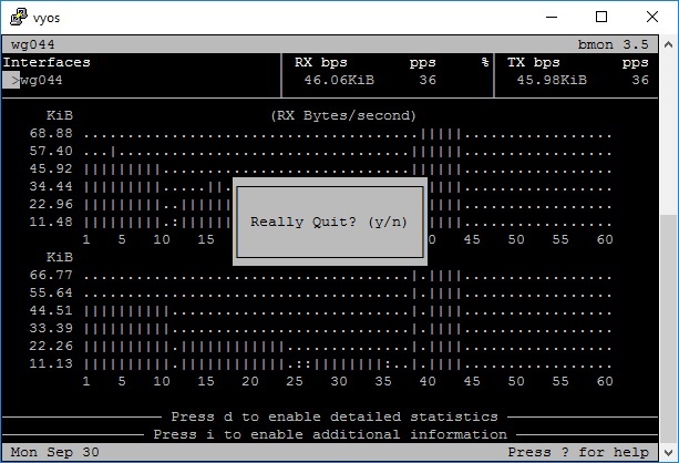
Further Discussions
- Join and discuss VyOS technology in VyOS Group.
- Ask related questions so that everyone has the opportunity to answer.
Have a question about something in this article? You can receive help directly from the article author. Sign up for a free trial to get started.
Comments (0)