
My favorite part of electronics design is circuit analysis and simulations. During my time working on metal oxide optoelectronics, I would routinely use a customized numerical solver for fitting theoretical circuit and component models to test devices.
Whether you are designing precision imaging systems, high-frequency electronic systems, or other high-speed systems, simulation tools are critical for designing, analyzing, and validating the functionality of your circuits for use in your next PCB. Most novice and veteran designers take advantage of a few standby simulations and analyses, but more complex systems require more complex analytical techniques. The function of your circuits can become as complex as your schematic and layout, so it is important to understand which simulation tools to use in different situations. Unfortunately, the marketing copy you'll find on many PCB design software company websites does not communicate this in the best way.
I've compiled a list of typical analyses you can find in most PCB design simulation packages, or that you can program on your own using SPICE or some other language. I've also listed what each of these tools can determine and why they are important in high-speed design. If you're interested in learning more about these different analysis techniques, then read on…
Types of PCB Design Simulation Tools
Time Domain vs. Frequency Domain
Before getting started, I think that it's important to note that one should distinguish between time domain and frequency domain simulations. First, each type of simulation will tell you different pieces of information about the behavior of your circuits. However, this does not mean that time domain simulations are exclusively used in circuit analysis for high-speed PCB design, nor does this mean that frequency domain simulations only tell you something about analog PCB design.
Each type of simulation has its place in each domain. Various PCB design simulation tools are designed to operate in specific domains, but they can be used to analyze circuits in either domain. In other words, using a frequency domain simulation for a digital circuit tells you something about the frequency components that make up a digital signal, while time domain simulations can tell you how the signal changes over time.
Linear vs. Nonlinear Circuits
This topic deserves its own article, both for digital signals, analog signals, and modulated signals. In general, a linear circuit is composed of purely linear circuit elements (e.g., resistors, capacitors, and inductors), while a nonlinear circuit contains at least one nonlinear element (e.g., diodes, transistors, and other semiconductor devices).
Nonlinear circuits will have a nonlinear relationship between the voltage and current in a circuit. Think about a diode; the current is an exponential function of voltage. This simple distinction between linear and nonlinear circuits is critical to understanding the right circuit simulation to use in different designs.
Certain PCB design simulation tools are designed to work with one or both types of circuits. Understanding this distinction and how different types of circuits relate to your simulation goal is very important for determining the right analytical technique to use. In some cases, nonlinear circuits can act like linear circuits, and understanding when this is the case can help you avoid drawing inaccurate conclusions about your design. Your PCB design simulation tools can typically be applied at the component level, as long as parasitics are properly considered.
Schematic vs. Layout Simulations
Circuit design and analysis tools are generally intended for use at the schematic level. This is an important point to understand in that circuit schematics and PCB layouts do not communicate the same information. Your PCB layout will determine parasitics in your board, which will affect the behavior of your board. Some effects produced in a real layout include crosstalk, conducted/radiated EMI, and transmission line effects.
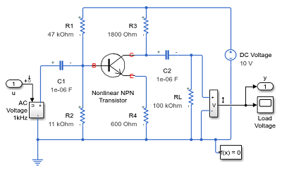
This circuit will act nonlinear once the input amplitude exceeds a certain threshold thanks to the presence of the transistor.
From here, we want to focus on circuit and system-level simulations, meaning PCB design simulation tools that are applied at the schematic level. Certain specialized simulation and analysis tools are designed to account for a 2D or quasi-2D PCB layout. More powerful simulation tools, such as 3D field solvers that run in the frequency and/or time domain, are designed to account for the real geometry of your layout.
As you start building successively more complex devices, you'll soon find that most circuit simulation tools are just not equipped to address issues like crosstalk, radiated EMI, power integrity, and other problems that arise due to parasitics. If you want to account for parasitics at the schematic level, then you need to include these parasitic circuit elements in your schematic simulations. EMWorks provides a decent guide on determining parasitics in your board in certain special situations. These processes help with certain aspects of transmission line design, including crosstalk due to coupling.
Which PCB Design Simulation Tools to Use and When
As much as I would like to get into depth on each of these subjects, it is beyond the scope of this article. My intention here is to give you a baseline for choosing the right circuit analysis technique to use in different situations. Hopefully, this will help you determine the best course to pursue for validating the functionality of your circuits.
Linearity-agnostic Analyses
In general, the response of any circuit in the time-domain can be calculated with finite difference methods. However, there are some specific tasks that can be performed, as shown below.
- DC sweep. This technique is designed to determine the functional relationship between a DC signal level and the response in a circuit. This can be used to determine when a circuit transitions from linear to nonlinear. This is a fundamental analysis for any circuit.
- Small-signal analysis. This technique is designed to approximate a circuit's response as a linear function around some operating point, so it is normally used to examine the behavior of nonlinear circuits driven with a single frequency. This is important for working with diodes, transistors, and other common nonlinear circuits.
- Sensitivity analysis. This technique is designed to examine how a circuit responds to tolerances in components. You can use this to determine which components in a circuit have the greatest effect on the response of your circuit.
- Monte Carlo simulations. This technique is ideal for linear or nonlinear circuits where analytical results cannot be derived easily. One example is for sensitivity analysis of nonlinear circuits. Component tolerances or variations in the input voltages can be treated as random variables, and thousands or millions of different possible values for the response in the circuit are calculated. The response can then be analyzed with standard statistical techniques.
- Time domain transient analysis. This technique can be applied to linear or nonlinear circuits driven with an arbitrary waveform. Note that Laplace-domain and Fourier domain transfer function analyses (which are related) only apply to linear circuits.
- Stability analysis. There are linear and nonlinear versions of stability analysis in the time and frequency domains. These analyses can also be applied to non-autonomous (i.e., time-variant) systems, although this is normally done in the time-domain. You can also perform these tasks analytically.
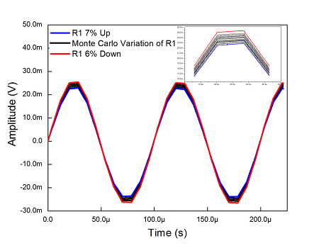
Results from a Monte Carlo sensitivity analysis simulation for an AC signal.
Linear Analyses
This set of techniques is fundamental in linear time-invariant circuit analysis:
- AC amplitude sweep. This is similar to a DC sweep, except it applies to the amplitude of an AC signal with a particular frequency. This is normally done in the frequency domain for linear circuits, but it can also be done in the time domain for nonlinear circuits using small-signal analysis (see above).
- Transfer function analysis. This is sometimes called pole-zero analysis as the goal is to determine the resonance frequencies and transient decay rates in a single simulation (called poles and zero, respectively). This is done in the Laplace domain. The other option is to work in the Fourier domain and calculate the phase and amplitude in the output response in the circuit, known together as the circuit's transfer function.
- Frequency sweep. This technique is similar to transfer function analysis in that you are determining the amplitude and phase of the circuit's response at different frequencies. Rather than deriving a specific functional form, you sweep through a range of frequencies numerically and calculate the amplitude and phase of the response.
- Power delivery network analysis. This is normally used to ensure that IR drop is minimized throughout a PCB's power delivery network. If you can include parasitics on your power rails, then you can perform this basic analysis to ensure power integrity.
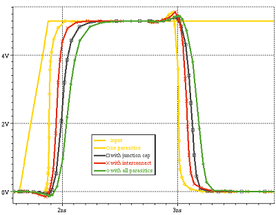
High speed PCB design simulation results showing timing jitter.
Nonlinear Analyses
Here are some important nonlinear analyses:
- Load-pull analysis. This particular analysis is used for determining the impedance seen by a nonlinear driver in a circuit. The input impedance the source sees may be different from the actual value of the load impedance when the source is nonlinear. An example application is in impedance matching for power amplifiers in RF signal chains.
- Harmonic balance analysis. This technique is designed to account for the fact that modulated analog signals experience intermodulation distortion in nonlinear circuits. This involves including a set of input frequencies at the driver of the circuit and calculating the spectrum seen at the output.
- Hysteresis analysis. Hysteretic circuits can create some interesting effects in the time-domain when driven with oscillating sources, although they may not be obvious until you plot the input-output curve for the circuit's response. Plotting the input-output curve from time-domain data can reveal the presence of any hysteresis in the circuit.
As high speed and high frequency devices continue to become more complex and functionality expands, working with a simulator package can help you better understand your system's performance. Simulation packages cannot build your board for you, but the results can provide some valuable insights into design changes that can boost performance and help you meet your design requirements. Once your simulator returns the results you're looking for, you can decide on the best design changes to improve the performance of your device.
SPICE models help with quick circuit analysis for larger circuits, but you'll have to manually create models that address issues that are important for circuit analysis for high-speed PCB design. Unless you can find models for every IC that appears in your board, you'll have to manually recreate logic circuits for use in your SPICE models. Instead, you'll want to use a simulator that goes beyond simpler SPICE models and incorporates a broad range of topologies, components, and structures.
Originally published at Northwest Engineering Solutions, October 7, 2019.
Have a question about something in this article? You can receive help directly from the article author. Sign up for a free trial to get started.
Comments (0)