Diagnose And Repair Your DC Power Jack On Your Laptop Mother Board


Published:
Browse All Articles > Diagnose And Repair Your DC Power Jack On Your Laptop Mother Board
When you hit the power button on your laptop and it does nothing there are a couple of things that you need to check. You will need to check your Ac Power Adapter and your DC Power Jack.
Tip: If you have checked your Ac power adapter and know it is good and
If you plug your AC power adapter in your DC power jack and press the power button and move the AC power adapter plug up and down and from side to side ,
and you see your lights trying to come on you have a bad DC power jack and can use the this article to learn how to repair the DC power jack.
Tools You will need.
1. Digital Multi Meter
2. Soldering Iron
3. Small Wire
4. Solder
5. Phillips screw driver to disassemble you laptop.
6. Solder paste flux.
Things you can learn from this article.
1. How to diagnose your DC power jack to see if it is bad.
2. How to repair your DC power jack.
If you can not solder you can practice on old motherboards until you are confident enough in your soldering ability's to try this.
You can at least learn how to use a digital multi meter to test your DC power jack and see if it is bad.
First thing is check the AC power adapter click the link below.
https://www.experts-exchange.com/Hardware/Laptops_Notebooks/A_3413-Check-Laptop-Power-Adapter-Voltage.html
Next Check your DC power jack .
The first thing you will need to do is disassemble your laptop down to the mother board. I will not go over how to disassemble your laptop down to motherboard level as that is out of the scope of this article.
Once you have your laptop disassembled down to the motherboard level you can start your inspection.
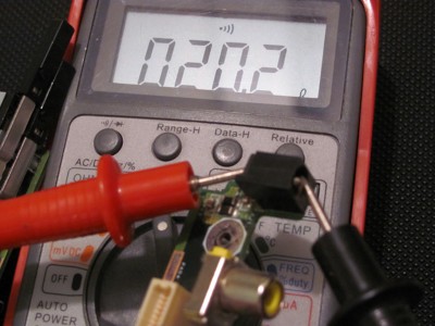
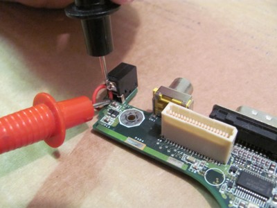
Get out your Digital Multi Meter and set it to the OHMS setting with the sound on (It makes a beep if you touch the black and red probes together). Find the center pin of the power jack and place one of your probes on the front of the pin and the other to the back of the DC power jack see photo below.
![Figure 1]()
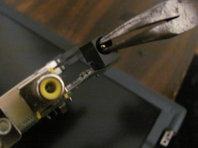
This center pin will often come loose and move from side to side and will be the cause of an open connection .You can check this with the multi meter with the sound on and see if it is a shared connection (Sound Beeps) or an open connection (NO Sound), and you can check this with small needle nose pliers. If it is loose you can repair it simply by applying flux and soldering the back . See photos below.
![Figure 2]()
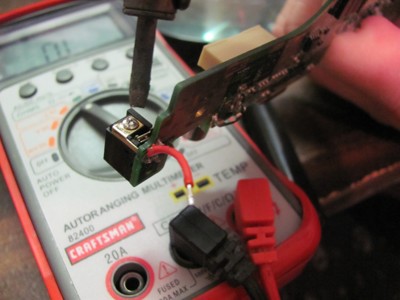
Next image is center pin repaired.
![Figure 3]()
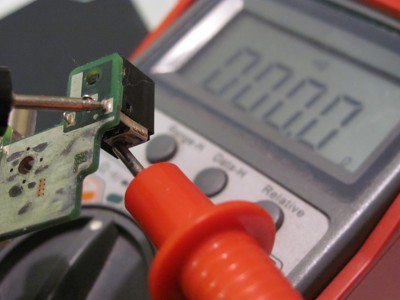
Once you have soldered the center pin check it with the need nose pliers again and confirm it is not loose anymore. Now check it with the multi meter and make sure its beeps when you touch the probes in the front and back .
![Figure 4]()
Once you confirm your connection is good from the front of the center pin to the back of the power jack next we will check out the connection from the back of the DC power jack center pin through the board to the bottom side of the board
This is a common place to have a problem at the through hole solder connection . Some times it is a bad solder joint, but most of the time it is from the stress of the Ac adapter power cord.. See image below.
![Figure 5]()
You can of course buy a new DC power jack and wait for it to come in but if there is a bad connection here I repair the problem area .
This is a good flexible repair and will hold up to stress better as the jumper wire is flexible. I have done lots of these repairs and not one has come back to me to repair again.
Sometimes the jumper wires are not needed you can just reflow (Put new solder ) on the back center pin and all the solder joints that go to the DC power jack . This can fix the jack lots of times.
You just have to learn to use the multi meter to check all the points on the DC power jack.
There are 2 ways you can run a jumper wire.
1. From the back of the center pin to the bottem of the mother board.
2. From the back of the center pin to a place on the trace on the board.
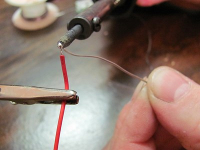
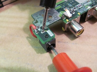
Fist thing is to fire up your soldering iron. Next strip some of the protective casing from your jumper wire and tin the end with solder.
Once you have completed that , solder the tined jumper wire to the bottom of the motherboard where the center pin comes through the hole on the motherboard. See red wire in the image below.
![Figure 6]()
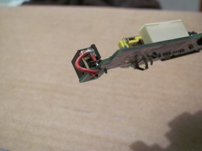
Next solder other end of wire to the back of the DC power jack center pin. See image below.
![Figure 7]()
The second method is to scratch out a place on the copper trace of the board and solder the jumper wire to that.
On this mother board the copper trace is on the top side of the board, lots of mother boards have the copper trace on the bottom of the mother board where the pin comes through the board.
Once you decide on a place use a small sharp pick and scratch of the coating to expose the copper on the trace. See the black arrow in the image below is where I did this repair.
Notice the green part is the protective coating on top of the copper. You can see the copper where I scratched off the green coating.
![Figure 8]()
I have saved allot of motherboards with this method especially when the through hole is mess up really bad.
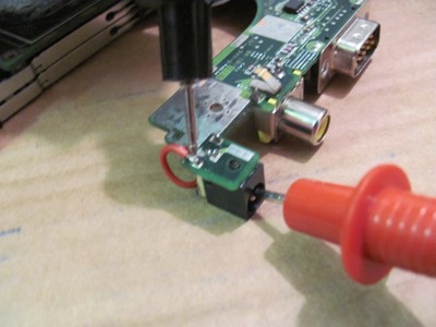
Once you have a place scratched out on the copper trace use your multi meter to check it. Place on probe on the front of center pin and other probe on the place you scratched of the copper trace. It should beep so you know it is sharing the connection.
Apply some solder flux to the coper this will help the solder stick to it. Now place some solder on your hot soldering iron, and touch it to the fluxed area. Now you will have a small solder ball on your trace.
Solder one end of your jumper wire to the solder ball you just made and the other to the back of the center pin of the dc power jack.
Example of both types of DC power jack repairs
![Figure 9]()
Now use your multi meter to check all your repairs. There should be beeps when you test the wires. See images below.
![Figure 10]()
![Figure 11]()
One last check is to check from the front of the center pin of the dc power jack to the ground on the bottom of the board.
There should be NO BEEPS with this check. You are checking to make sure there is no short in your work. See Image Below.
![Figure 12]()
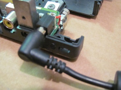
Here is board back in bottom tray of laptop. See image below.
![Figure 13]()
Tip: If you have checked your Ac power adapter and know it is good and
If you plug your AC power adapter in your DC power jack and press the power button and move the AC power adapter plug up and down and from side to side ,
and you see your lights trying to come on you have a bad DC power jack and can use the this article to learn how to repair the DC power jack.
Tools You will need.
1. Digital Multi Meter
2. Soldering Iron
3. Small Wire
4. Solder
5. Phillips screw driver to disassemble you laptop.
6. Solder paste flux.
Things you can learn from this article.
1. How to diagnose your DC power jack to see if it is bad.
2. How to repair your DC power jack.
If you can not solder you can practice on old motherboards until you are confident enough in your soldering ability's to try this.
You can at least learn how to use a digital multi meter to test your DC power jack and see if it is bad.
First thing is check the AC power adapter click the link below.
https://www.experts-exchange.com/Hardware/Laptops_Notebooks/A_3413-Check-Laptop-Power-Adapter-Voltage.html
Next Check your DC power jack .
The first thing you will need to do is disassemble your laptop down to the mother board. I will not go over how to disassemble your laptop down to motherboard level as that is out of the scope of this article.
Once you have your laptop disassembled down to the motherboard level you can start your inspection.
Get out your Digital Multi Meter and set it to the OHMS setting with the sound on (It makes a beep if you touch the black and red probes together). Find the center pin of the power jack and place one of your probes on the front of the pin and the other to the back of the DC power jack see photo below.
This center pin will often come loose and move from side to side and will be the cause of an open connection .You can check this with the multi meter with the sound on and see if it is a shared connection (Sound Beeps) or an open connection (NO Sound), and you can check this with small needle nose pliers. If it is loose you can repair it simply by applying flux and soldering the back . See photos below.
Next image is center pin repaired.
Once you have soldered the center pin check it with the need nose pliers again and confirm it is not loose anymore. Now check it with the multi meter and make sure its beeps when you touch the probes in the front and back .

Once you confirm your connection is good from the front of the center pin to the back of the power jack next we will check out the connection from the back of the DC power jack center pin through the board to the bottom side of the board
This is a common place to have a problem at the through hole solder connection . Some times it is a bad solder joint, but most of the time it is from the stress of the Ac adapter power cord.. See image below.
You can of course buy a new DC power jack and wait for it to come in but if there is a bad connection here I repair the problem area .
This is a good flexible repair and will hold up to stress better as the jumper wire is flexible. I have done lots of these repairs and not one has come back to me to repair again.
Sometimes the jumper wires are not needed you can just reflow (Put new solder ) on the back center pin and all the solder joints that go to the DC power jack . This can fix the jack lots of times.
You just have to learn to use the multi meter to check all the points on the DC power jack.
There are 2 ways you can run a jumper wire.
1. From the back of the center pin to the bottem of the mother board.
2. From the back of the center pin to a place on the trace on the board.
Fist thing is to fire up your soldering iron. Next strip some of the protective casing from your jumper wire and tin the end with solder.
Once you have completed that , solder the tined jumper wire to the bottom of the motherboard where the center pin comes through the hole on the motherboard. See red wire in the image below.
Next solder other end of wire to the back of the DC power jack center pin. See image below.
The second method is to scratch out a place on the copper trace of the board and solder the jumper wire to that.
On this mother board the copper trace is on the top side of the board, lots of mother boards have the copper trace on the bottom of the mother board where the pin comes through the board.
Once you decide on a place use a small sharp pick and scratch of the coating to expose the copper on the trace. See the black arrow in the image below is where I did this repair.
Notice the green part is the protective coating on top of the copper. You can see the copper where I scratched off the green coating.

I have saved allot of motherboards with this method especially when the through hole is mess up really bad.
Once you have a place scratched out on the copper trace use your multi meter to check it. Place on probe on the front of center pin and other probe on the place you scratched of the copper trace. It should beep so you know it is sharing the connection.
Apply some solder flux to the coper this will help the solder stick to it. Now place some solder on your hot soldering iron, and touch it to the fluxed area. Now you will have a small solder ball on your trace.
Solder one end of your jumper wire to the solder ball you just made and the other to the back of the center pin of the dc power jack.
Example of both types of DC power jack repairs

Now use your multi meter to check all your repairs. There should be beeps when you test the wires. See images below.
One last check is to check from the front of the center pin of the dc power jack to the ground on the bottom of the board.
There should be NO BEEPS with this check. You are checking to make sure there is no short in your work. See Image Below.
Here is board back in bottom tray of laptop. See image below.
Have a question about something in this article? You can receive help directly from the article author. Sign up for a free trial to get started.
Comments (2)
Commented:
I haven't gone through the rest, as I've only done this a couple of times to obvious broken solder points or cracked jacks. Didn't need to do much but solder the replacement on then plug it in.
Commented: