Configure T1 and Cable for failover
I've search the knowledge base and found many articles on Cisco fail over methods but I'm still confused. What I'm attempting to do is to setup a backup circuit for our Main office and 3 remote offices. Currently we are using T1 for inter branch connectivity for VOIP and data. All traffic comes to the Main office and goes on it's merry way. Traffic is defined as such; a separate router and firewall for Internet, a separate router provided by our data processor (we're a CU). All file servers, email etc are at our Main Office. We're implementing a backup server solution at one of our branches at a later date.
Our primary circuit is a T1 using MPLS.
Our secondary circuit is Cable (also drives our ATM's).
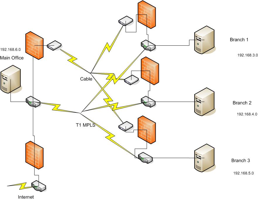
A basic diagram is;
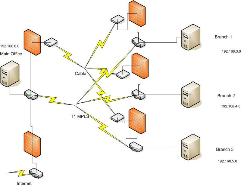
The data path though the Cable is a VPN and the firewalls take care of all VPN functions
Routers are 2811's with a T1 and 2 ethernet interfaces.
The default GW for Site 1 to the backup circuit is 97.77.118.25
The default GW for Site 2 to the backup circuit is 97.77.118.41
The main routers config looks like this,
version 12.4
no service pad
service tcp-keepalives-in
service tcp-keepalives-out
service timestamps debug datetime msec localtime show-timezone
service timestamps log datetime msec localtime show-timezone
service password-encryption
service sequence-numbers
!
hostname Site1-2811
!
boot-start-marker
boot-end-marker
!
logging buffered 4096 informational
enable secret 5 **************
no aaa new-model
clock timezone CST -6
clock summer-time CDT recurring
no ip source-route
!
!
ip cef
!
!
no ip bootp server
no ip domain lookup
ip domain name texaspartnersfcu.org
!
username admin privilege 15 secret 5 **************
!
!
ip tcp synwait-time 10
!
class-map match-any VOIP-Traffic
match access-group name QoS-VoIP-RTP
class-map match-any VOIP-Control
match access-group name QoS-VoIP-Control
!
!
policy-map QOS-Out
class VOIP-Traffic
priority percent 70
class VOIP-Control
bandwidth percent 5
class class-default
fair-queue
!
!
!
interface FastEthernet0/0
description Site1 LAN
ip address 192.168.6.27 255.255.255.0
no ip redirects
no ip unreachables
no ip proxy-arp
no ip mroute-cache
duplex auto
speed auto
!
interface FastEthernet0/1
ip address 192.168.20.1 255.255.255.0
no ip redirects
no ip unreachables
no ip proxy-arp
ip route-cache flow
duplex auto
speed auto
!
interface Serial0/0/0
ip address 172.21.235.114 255.255.255.252
no ip mroute-cache
service-module t1 timeslots 1-24
service-module t1 remote-alarm-enable
service-module t1 fdl both
no cdp enable
service-policy output QOS-Out
!
router eigrp 100
redistribute static
network 172.21.0.0
network 192.168.1.0
network 192.168.20.0
no auto-summary
!
ip route 0.0.0.0 0.0.0.0 192.168.1.4
ip route 0.0.0.0 0.0.0.0 192.168.6.12
ip route 172.20.0.0 255.255.0.0 192.168.6.20
!
ip http server
!
ip access-list extended QoS-VoIP-Control
permit udp any any eq 2427
permit udp any any eq 2727
permit udp any any range 5440 5445
ip access-list extended QoS-VoIP-RTP
permit udp any any eq 5004
permit udp any any eq 5005
!
logging trap debugging
logging source-interface FastEthernet0/0
logging 192.168.6.4
snmp-server community **** RO
snmp-server community ***** RW
!
control-plane
!
!
line con 0
line aux 0
line vty 0 4
!
line vty 5 15
password 7 ********
login
!
scheduler allocate 20000 1000
!
end
And here is one of our remote sites;
version 12.4
no service pad
service tcp-keepalives-in
service tcp-keepalives-out
service timestamps debug datetime msec localtime show-timezone
service timestamps log datetime msec localtime show-timezone
service password-encryption
service sequence-numbers
!
hostname Site2-2811
!
boot-start-marker
boot-end-marker
!
logging buffered 4096 informational
enable secret 5 ***********
!
no aaa new-model
clock timezone CST -6
clock summer-time CDT recurring
no ip source-route
!
!
ip cef
!
!
no ip bootp server
no ip domain lookup
ip domain name texaspartnersfcu.org
!
username admin privilege 15 secret 5 *************
!
!
ip tcp synwait-time 10
!
class-map match-any VOIP-Traffic
match access-group name QoS-VoIP-RTP
class-map match-any VOIP-Control
match access-group name QoS-VoIP-Control
!
!
policy-map QOS-Out
class VOIP-Traffic
priority percent 70
class VOIP-Control
bandwidth percent 5
class class-default
fair-queue
!
!
interface FastEthernet0/0
description Site2 LAN
ip address 192.168.4.12 255.255.255.0
no ip redirects
no ip unreachables
no ip proxy-arp
no ip mroute-cache
duplex auto
speed auto
!
interface FastEthernet0/1
ip address 192.168.24.1 255.255.255.0
no ip redirects
no ip unreachables
no ip proxy-arp
ip route-cache flow
duplex auto
speed auto
!
interface Serial0/0/0
ip address 172.21.235.118 255.255.255.252
no ip mroute-cache
service-module t1 timeslots 1-24
service-module t1 remote-alarm-enable
service-module t1 fdl both
no cdp enable
service-policy output QOS-Out
!
router eigrp 100
redistribute connected
network 172.21.0.0
network 192.168.4.0
network 192.168.24.0
no auto-summary
!
ip route 0.0.0.0 0.0.0.0 172.21.235.117
!
ip http server
!
ip access-list extended QoS-VoIP-Control
permit udp any any eq 2427
permit udp any any eq 2727
permit udp any any range 5440 5445
ip access-list extended QoS-VoIP-RTP
permit udp any any eq 5004
permit udp any any eq 5005
!
logging source-interface FastEthernet0/0
logging 192.168.6.4
snmp-server community tpfcu RO
!
control-plane
!
!
line con 0
line aux 0
line vty 0 4
password 7 ********
login
line vty 5 15
password 7 *********
permit udp any any eq 5004
permit udp any any eq 5005
!
logging source-interface FastEthernet0/0
logging 192.168.6.4
snmp-server community ***** RO
!
control-plane
!
!
line con 0
line aux 0
line vty 0 4
password 7 *********
login
line vty 5 15
password 7 **********
login
!
scheduler allocate 20000 1000
!
end
I hope I've provided enough information. I have been working on this for awhile and would appreciate all the help and expertise.
Thanks Richard
Reduntant-Circuit.vsd
Our primary circuit is a T1 using MPLS.
Our secondary circuit is Cable (also drives our ATM's).
A basic diagram is;
The data path though the Cable is a VPN and the firewalls take care of all VPN functions
Routers are 2811's with a T1 and 2 ethernet interfaces.
The default GW for Site 1 to the backup circuit is 97.77.118.25
The default GW for Site 2 to the backup circuit is 97.77.118.41
The main routers config looks like this,
version 12.4
no service pad
service tcp-keepalives-in
service tcp-keepalives-out
service timestamps debug datetime msec localtime show-timezone
service timestamps log datetime msec localtime show-timezone
service password-encryption
service sequence-numbers
!
hostname Site1-2811
!
boot-start-marker
boot-end-marker
!
logging buffered 4096 informational
enable secret 5 **************
no aaa new-model
clock timezone CST -6
clock summer-time CDT recurring
no ip source-route
!
!
ip cef
!
!
no ip bootp server
no ip domain lookup
ip domain name texaspartnersfcu.org
!
username admin privilege 15 secret 5 **************
!
!
ip tcp synwait-time 10
!
class-map match-any VOIP-Traffic
match access-group name QoS-VoIP-RTP
class-map match-any VOIP-Control
match access-group name QoS-VoIP-Control
!
!
policy-map QOS-Out
class VOIP-Traffic
priority percent 70
class VOIP-Control
bandwidth percent 5
class class-default
fair-queue
!
!
!
interface FastEthernet0/0
description Site1 LAN
ip address 192.168.6.27 255.255.255.0
no ip redirects
no ip unreachables
no ip proxy-arp
no ip mroute-cache
duplex auto
speed auto
!
interface FastEthernet0/1
ip address 192.168.20.1 255.255.255.0
no ip redirects
no ip unreachables
no ip proxy-arp
ip route-cache flow
duplex auto
speed auto
!
interface Serial0/0/0
ip address 172.21.235.114 255.255.255.252
no ip mroute-cache
service-module t1 timeslots 1-24
service-module t1 remote-alarm-enable
service-module t1 fdl both
no cdp enable
service-policy output QOS-Out
!
router eigrp 100
redistribute static
network 172.21.0.0
network 192.168.1.0
network 192.168.20.0
no auto-summary
!
ip route 0.0.0.0 0.0.0.0 192.168.1.4
ip route 0.0.0.0 0.0.0.0 192.168.6.12
ip route 172.20.0.0 255.255.0.0 192.168.6.20
!
ip http server
!
ip access-list extended QoS-VoIP-Control
permit udp any any eq 2427
permit udp any any eq 2727
permit udp any any range 5440 5445
ip access-list extended QoS-VoIP-RTP
permit udp any any eq 5004
permit udp any any eq 5005
!
logging trap debugging
logging source-interface FastEthernet0/0
logging 192.168.6.4
snmp-server community **** RO
snmp-server community ***** RW
!
control-plane
!
!
line con 0
line aux 0
line vty 0 4
!
line vty 5 15
password 7 ********
login
!
scheduler allocate 20000 1000
!
end
And here is one of our remote sites;
version 12.4
no service pad
service tcp-keepalives-in
service tcp-keepalives-out
service timestamps debug datetime msec localtime show-timezone
service timestamps log datetime msec localtime show-timezone
service password-encryption
service sequence-numbers
!
hostname Site2-2811
!
boot-start-marker
boot-end-marker
!
logging buffered 4096 informational
enable secret 5 ***********
!
no aaa new-model
clock timezone CST -6
clock summer-time CDT recurring
no ip source-route
!
!
ip cef
!
!
no ip bootp server
no ip domain lookup
ip domain name texaspartnersfcu.org
!
username admin privilege 15 secret 5 *************
!
!
ip tcp synwait-time 10
!
class-map match-any VOIP-Traffic
match access-group name QoS-VoIP-RTP
class-map match-any VOIP-Control
match access-group name QoS-VoIP-Control
!
!
policy-map QOS-Out
class VOIP-Traffic
priority percent 70
class VOIP-Control
bandwidth percent 5
class class-default
fair-queue
!
!
interface FastEthernet0/0
description Site2 LAN
ip address 192.168.4.12 255.255.255.0
no ip redirects
no ip unreachables
no ip proxy-arp
no ip mroute-cache
duplex auto
speed auto
!
interface FastEthernet0/1
ip address 192.168.24.1 255.255.255.0
no ip redirects
no ip unreachables
no ip proxy-arp
ip route-cache flow
duplex auto
speed auto
!
interface Serial0/0/0
ip address 172.21.235.118 255.255.255.252
no ip mroute-cache
service-module t1 timeslots 1-24
service-module t1 remote-alarm-enable
service-module t1 fdl both
no cdp enable
service-policy output QOS-Out
!
router eigrp 100
redistribute connected
network 172.21.0.0
network 192.168.4.0
network 192.168.24.0
no auto-summary
!
ip route 0.0.0.0 0.0.0.0 172.21.235.117
!
ip http server
!
ip access-list extended QoS-VoIP-Control
permit udp any any eq 2427
permit udp any any eq 2727
permit udp any any range 5440 5445
ip access-list extended QoS-VoIP-RTP
permit udp any any eq 5004
permit udp any any eq 5005
!
logging source-interface FastEthernet0/0
logging 192.168.6.4
snmp-server community tpfcu RO
!
control-plane
!
!
line con 0
line aux 0
line vty 0 4
password 7 ********
login
line vty 5 15
password 7 *********
permit udp any any eq 5004
permit udp any any eq 5005
!
logging source-interface FastEthernet0/0
logging 192.168.6.4
snmp-server community ***** RO
!
control-plane
!
!
line con 0
line aux 0
line vty 0 4
password 7 *********
login
line vty 5 15
password 7 **********
login
!
scheduler allocate 20000 1000
!
end
I hope I've provided enough information. I have been working on this for awhile and would appreciate all the help and expertise.
Thanks Richard
Reduntant-Circuit.vsd
ASKER
Ok, I might not have explained it very well so I'll rephrase what I said before.
Original setup is Local Branch Office (6.0 subnet) -> branch router -> MPLS -> Remote Branch Router -> Remote local segment (4.0 subnet). This is repeated 2 more times to the other branches. Each branch has their own subnet.
New setup will include the original setup plus. Route for VPN is Local Branch Office (6.0) -> Branch router -> Local Firewall (+VPN) -> Internet -> Remote Firewall (VPN) -> Remote Branch Router -> Remote local subnet (4.0) and again repeated 2 more times for the other branches.
The failover mechanism will take place in the 2811 routers.
Thanks.
Ok, so you have the cable connection going into the 2811 at each side on FastEthernet?
The 2811 has a VPN policy to the other branches using the cable IP for the connection?
i.e. the VPN peer is the CABLE IP since this is the only way to get to the Internet.
Where is the 172.21.235.117 coming from?
You should look into configuring OSPF over the MPLS and over the VPN.
When the connection on the MPLS drops, the paths will drop off as well and leave the only way to get to the other side through the VPN.
The problem is that you are setting the default route
ip route 0.0.0.0 0.0.0.0 172.x.y.z
which directs all traffic through presumably the MPLS link.
You only want to send MPLS destined traffic through the MPLS link which OSPF setup will accomplish.
For failover to work, you can not have static routes, you have to have routes that adjust with conditions i.e
ip route 192.168.4.0 255.255.255.0 FastEthernet0/0/0
This route will be dropped when the FastEthernet0/0/0 drops/looses link.
ASKER
The 2811 does not do the VPN that is handled in the firewall prior to the cable modem. The 172.x.x.x traffic is WAN side of the MPLS. I do know I have a routing issue on the 192.168.20.1 (FE0/1) as when these routers were first installed that interface "was" to be use for our VOIP phones (didn't happen). I also from reading understand that some IP traffice "may" be dropped when the circuits switch over and that is an unfortunate result of having two different ISPs involved and will have to live with that for now. I may be able to minimize that by doing more of a load balance/failover rather than a straight failover.
You will need to utilize a GRE tunnel if you plan to do any type of routing; I imagine that the MPLS network for the T1s are transparent to you (Meaning that you are not participating in any MPLS configurations on your routers, etc). Depending on the type of services your T1 provider supports, they might not be setup or allow routing protocols via their MPLS networks (Something I have seen in the past, provider only supported static routing). All sites will need to support the concept of a GRE tunnel, this is needed for any type of dynamic routing you will be utilizing. What kind of firewall is installed (Make and model). Furthermore, you are still setup for single point of failure, your redundancy exists only for the physical connections to the main brach from the remote sites. I would recommend installing a switch for dedicated connections from the firewall and router; though you will have to then consider a layer 3 redundant protocol like VRRP or HSRP. So without any additional information, it is hard to provide a solid solution.
Billy
Billy
ASKER
rfc1180 - for the backup circuits we're using watchguards 10e and they are currently configured to do branch VPN. Also I do agree with the single point of failure. It's taking me several years to get this far (WAN redundency). Now I do believe some new routing tables will need to be created and I believe that duplicating the 0.0.0.0 0.0.0.0 172.x.x.x with 0.0.0.0 0.0.0.0 97.77.118.x will be needed. As far as the rest I'm not sure. Did I mention that when it comes to configuring routers I'm a novice? I know enough to get myself in trouble as I just don't do it enough to become/stay proficient.
Richard, no worries, I used to know enough to get myself in trouble as well; we all were there. I just wanted to make sure it was thrown out there. That is the problem with static routing, static routing breaks redundancy in some cases; I would highly recommend a routing protocol between ALL sites. I am not familiar with the watchguards, but like Cisco and Juniper they should support some type of GRE tunnel that you layer IPSEC with. This will allow the dynamic protocols to function via the VPN.
Billy
Billy
I do not believe automatic failover is possible if a dynamic routing update, setting up a tunnel over the MPLS might be wasting resources as well as over the cable connection though could be a way to handle this, the only issue is that the GRE will let the branches bypass the firewall.
Cisco has several GRE configuration example including IPSEC+gre routing with OSPF.
http://www.cisco.com/en/US/tech/tk827/tk369/tk287/tsd_technology_support_sub-protocol_home.html
Here is an example of QoS that might be of interest to you to minimize the impact on essential functionlity if the MPLS connection drops.
The first link below deals with QoS for VOIP including the 2811. The second as the file states deals with QoS over an MPLS network including the 2811.
http://support.avaya.com/css/P8/documents/003959018
https://devconnect.avaya.com/public/flink.do?f=/public/download/interop/G450_QOS_MPLS.pdf
The author can't setup a MPLS tunnel as there are no MPLS services at his edge routers. The MPLS that does exist, only exists in the Telco cloud which is transparent to the author. I am sure any additional services the author adds will be an additional fee. Secondly, failover is definitely possible with any dynamic routing protocol if there is more than one path to a destination; however, routing protocols can not detect RIB/FIB failure and fine tuning ip routing protocols too low can create instability in your core network; the addition of BFD and IP SLA would be appropriate.
As far as the GRE traffic is concerned regarding bypassing the firewall, it depends on the vendor chosen; if utilizing the Cisco IOS Firewall features, Cisco SPI inspects the packet after it passes an inbound ACL of an input interface and if ip inspect in is applied. It also applies after the outbound ACL of output interface and if ip inspect out is used. At this point, Firewall SPI features can inspect traffic traversing a GRE tunnel as it is inspected after passing an ACL; so if you have a Cisco router that supports the firewall feature set, you should be set.
Sources:
http://www.ciscosistemas.org/en/US/prod/collateral/vpndevc/ps5708/ps5710/ps1018/prod_qas09186a008010a40e.pdf
http://www.cisco.com/en/US/prod/collateral/vpndevc/ps5708/ps5710/ps1018/product_implementation_design_guide09186a00800fd670.html
http://www.netcordia.com/community/blogs/terrys_blog/archive/2010/11/08/real-time-network-failure-detection.aspx
Billy
ASKER
Right, the MPLS is transparent to me as I just see a connection between sites. as far as multiple routes to all branches that's is an idea that I've thought about but until I get the basics setup..... I'm not sure which protocol would handle my problem best. What I've envisioned is a protocol that would detect connectivity (maybe pings) and then switch circuits. I can stand a short disruption but not much. Our IOS for the 2811's are pretty basic i.e. there isn't any firewall or VPN additions so anything like that is handled outside of the router. I will look over those documents presented so far and get back to everyone. It's going to take me a couple of days though as I'm slammed with other fires at this moment. Thank you everyone so far.
> I'm not sure which protocol would handle my problem best. What I've envisioned is a protocol that would detect connectivity (maybe pings) and then switch circuits.
you can ise IP SLA
Additionally, dynamic routing can be used in conjunction with IP SLA; you could use OSPF if you have the resources, if not EIGRP would be the next protocol, but I would not use RIP or IS-IS. IS-IS is a great protocol, but as there is not much of a community for it, I will not recommend it. OSPF is a much more open standard than IS-IS.
Billy
ASKER
In looking at my configurations it looks like I have EIGRP already configured (maybe). I like the idea of OSPF and would be interested in the comparison. IP-SLA I'm not familiar with at all. I agree RIP would be my last choice. IS-IS???? Never heard of it so I guess that's out.
Richard
Richard
you do have EIGRP configured, but what abou the rest of the network; you will need to make that decision on which path you take. Note, that EIGRP is NOT an open standard and you will not be able to use third part y hardware and peer with another Cisco router running EIGRP. So if you have any other hardware that is NOT Cisco, you will need to migrate to OSPF or redistribute from one protocol to another.
Billy
Billy
ASKER
All of our routers are Cisco 2811's for the branch connectivity. Basically I'll be failing over from SE0/0/0 to FE0/1.
so just configuring the rest of the routers utilizing EIGRP and then configure the interfaces to be assigned to the routing process. Again, as already stated, you can use BFD and IP SLA inconjuction with the routing protocol to allow seamless failover with sub-milliseconds convergence.
http://www.cisco.com/en/US/technologies/tk648/tk365/tk207/technologies_white_paper0900aecd80243fe7_ps6599_Products_White_Paper.html
Billy
http://www.cisco.com/en/US/technologies/tk648/tk365/tk207/technologies_white_paper0900aecd80243fe7_ps6599_Products_White_Paper.html
Billy
ASKER
OK, looking at the documentation you provided and we'll see where it takes me. Should be able to get back to you tomorrow. Again thanks.
ASKER
OK, finished looking over the documentation on BFD. How do I know that my 2811s support this?
http://tools.cisco.com/ITDIT/CFN/jsp/index.jsp
search by your image (Show version)
or search by feature (BFD) I believe that there is a specific feature set for BFD with EIGRP support but if I am not mistaken, the ASR1000 and another platform is the only platforms that are available specifically to that feature set, so you might have to settle with the standard BFD support.
Billy
ASKER
Looks like I don't support BFD (go figure) My version is; Cisco IOS Software, 2800 Software (C2800NM-IPBASE-M), Version 12.4(13b), RELEAS).
So where do I go from here?
One thing I'm trying to setup is using the backup routers (spares) setting up a test enviroment so I can implement changes without affecting our production routers. This is assuming that I can get the WANS to take to each other.
So where do I go from here?
One thing I'm trying to setup is using the backup routers (spares) setting up a test enviroment so I can implement changes without affecting our production routers. This is assuming that I can get the WANS to take to each other.
You do not need BFD to move forward, it is option for quicker failover.
you can move forward here:
http://www.cisco.com/en/US/docs/ios/12_2/ip/configuration/guide/1cfeigrp.html#wp1004191
There are some examples depending on the route you take. To be really honest, using EIGRP and multihoming Ethernet and T1s will be painless; you really do not need to set it up in the lab. Configure and connect, EIGRP will use the fast link for traffic and in this case, the T1 will not even be used, so no reconvergence should occur. However, I will still add the equipment in a maintenance window.
Those static routes are going to kill your failover; you will want to run EIGRP on ALL routers/firewalls in your network. I am not sure if the watchguards are capable of this, but typically you will need a protocol such as GRE for a tunnel to be used for routing. I would start there; if the watchguards are configured for the VPN, is EIGRP enabled on the watchguards (Does not appear so from the config); but if you are adding static routes for a reason (Watchguards do not support EIGRP), you are going to have to rely on IP SLA for your failover, which will be a headache on a network like yours.
Billy
Billy
ASKER
Great, reading the doc now. Test enviroment about ready. Wasn't sure I could get the two routers to talk via the T1 Wic but a simple cross cable is all it needs. Setting up some virtual servers to act as the endpoints. After reading the docs I'll get back with you. And I really want to express my graditute at this point in your assistance. I be learning......:)
ASKER
OK, Thanks for waiting:) Setup test environment and using EIGRP was able to setup my primary and backup circuits. Ran a server on each end and can see by doing a never ending ping was able to fail over the circuits in both directions which is great. But (there's always a but) because in my real world environment my backup circuit is faster than my primary circuit EIGRP is going to use it first. Normally I wouldn't mind this and it may be the way we'll go eventually but because our backup circuits have some ATM's hanging off of them and until I can measure some performance etc. I want to keep using the primary circuit as the primary. I believe I can set some metrics on the interfaces to prioritize the traffice to the primary link. Is that true? And if so where and how much?
Again thanks.
Again thanks.
Even though the preferred path right now is on a slower link, you can control the routing by configuring the faster path with a higher cost.
ASKER
Been looking at the "Delay" metric but wanted further clarifcation first and or other options.
Other options?
http://www.cisco.com/en/US/docs/ios/12_0/np1/configuration/guide/1ceigrp.html#wp4692
IF you could provide details on the clarification you are looking for?
http://www.cisco.com/en/US/docs/ios/12_0/np1/configuration/guide/1ceigrp.html#wp4692
IF you could provide details on the clarification you are looking for?
ASKER
Yep, read that document. That's where I found out about delay etc. Going back to my original drawing and can see where it's pretty confusing. I'll redraw and post again with a more simplified version.
To avoid complication use a two/three node example. The settings between/among these nodes will be replicated to the others.
ASKER
OK.
ASKER
OK, hope this is more of a simplified picture. At this time I want to weight the traffic to still use the primary route. Without weighting I know that the routers will default to the VPN circuit which is faster. I have internal reasons for keeping the primary route as the main pipeline. At this time from what I've been reading on the advice from people here I most likely need to use the delay metric as the other possibilities may impact the data too much. If there is another, possibly better way to perform this?
Redundant-circuit-simplified.jpg
Redundant-circuit-simplified.jpg
The problem is do you know what the delay treshhold you need to set?
http://www.cisco.com/en/US/tech/tk365/technologies_tech_note09186a00800c2d96.shtml#delayparaR4
You can start low with 50 microseconds as a delay on the Cable connection (Fe0/1) and see if that will change the ip route table in favor of the primary you want.
You might want to delay it in such a way that if there is too much traffic that it will reroute over the other connection to behave somewhat as a load balancer versus a failover.
I.e. when traffic on the T1 hits 60% the delay inherent in it might lend the other Delayed connection to now become better and will have some of the traffic flow through that path.
ASKER
I like your idea about the 60%. Let me get some real world delays on the T1. Currently on the production routers I have the VPN side disabled and will need to setup the routing and get that to work so I can get some delay metrics on that also. As a lot of this will have to happen after hours I hope to get back within the next 48 hours.
TIA
TIA
ASKER
OK, tried the route statements (ip route 0.0.0.0 0.0.0.0 192.168.25.2) on site A and (ip route 0.0.0.0 0.0.0.0 192.168.20.2) on site A and ended up causing problems. Site b computers no longer could see site A's servers. I did notice that the VPN circuits didn't fire up as expected. Looks like I'll need to troubleshoot my VPN circuits some more before continuing.
Is there a way to place this question on hold or should I go ahead and award points and then re-address this after i can confirm I've got a good connection with the VPN?
Is there a way to place this question on hold or should I go ahead and award points and then re-address this after i can confirm I've got a good connection with the VPN?
You should not use IPs as that will make the routing rule static. You want to use the interface which will mean the routing table will be dynamically adjusted should the interface go down.
A single route as you've shown means there is no failover.
For failover/loadbalance you need two routes.
The other issue you were trying to deal with was inter-branch communication, so you need to deal with the specific IP sement routing
if your sitea
ip route 192.168.2.0 255.255.255.0 192.168.25.2
and on the other
ip route 192.168.3.0 255.255.255.0 192.168.20.2
The default route you set, adversely affected the VPN connection because of the route the VPN was being directed to 192.168.25.2 as the gateway to reach the external IP for which the VPN was configured.
ASKER
OK, for now disregard my VPN issue. You've got me confused. Currently the route from Site B to Site A is ip route 0.0.0.0 0.0.0.0 172.21.235.117 which is the T1.
Site A has;
ip route 0.0.0.0 0.0.0.0 192.168.1.4 -> INET router
ip route 0.0.0.0 0.0.0.0 192.168.6.12 -> Firewall to INET
ip route 172.20.0.0 255.255.0.0 192.168.6.20 -> router to our data host
-----------------------
So for the moment assuming my VPN worked.
I added to Site B
ip route 0.0.0.0 0.0.0.0 192.168.24.2 -> which goes to the VPN connection
-------------------------
Also note that Site A has this for EIGRP
router eigrp 100
redistribute static
network 172.21.0.0
network 192.168.1.0
network 192.168.20.0
no auto-summary
And Site B has this for EIGRP
router eigrp 100
redistribute connected
network 172.21.0.0
network 192.168.4.0
network 192.168.24.0
no auto-summary
---------------------
So this is where I'm getting confused, According to Cisco documentation I should have a "ip route" on both Sites pointing to each other yet on my routers that's not the case. Also keep in mind that everything is working correctly at this time. I'm confused because when I add the route which DOES work on my backup routers (has the same configuration) failover works.
Why did you disable the auto-summary?
show ip route?
http://www.cisco.com/en/US/tech/tk365/technologies_tech_note09186a00800c2d96.shtml
http://www.cisco.com/en/US/docs/ios/12_0/np1/command/reference/1reigrp.html
You do not need to define routes, you would let EIGRP advertise and update the routing table.
When you set the routers in a test, did they have an external feed and then LANs that are not accessible through the first feed?
You might not have matched the test environment to the one you are trying to setup.
ASKER
The vendor who initially configured the routers disabled auto-summary (don't know what it does anyway).
-----
ip route Site A
Gateway of last resort is 192.168.6.12 to network 0.0.0.0
D 192.168.24.0/24 [90/2693120] via 172.21.235.113, 1w0d, Serial0/0/0
172.21.0.0/30 is subnetted, 4 subnets
C 172.21.235.112 is directly connected, Serial0/0/0
D 172.21.235.116 [90/2690560] via 172.21.235.113, 1w0d, Serial0/0/0
D 172.21.235.120 [90/2690560] via 172.21.235.113, 7w0d, Serial0/0/0
D 172.21.235.148 [90/2690560] via 172.21.235.113, 5w6d, Serial0/0/0
S 172.20.0.0/16 [1/0] via 192.168.6.20
D 192.168.4.0/24 [90/2693120] via 172.21.235.113, 1w0d, Serial0/0/0
C 192.168.20.0/24 is directly connected, FastEthernet0/1
D 192.168.5.0/24 [90/2693120] via 172.21.235.113, 5w6d, Serial0/0/0
C 192.168.6.0/24 is directly connected, FastEthernet0/0
D 192.168.3.0/24 [90/2693120] via 172.21.235.113, 2w5d, Serial0/0/0
S* 0.0.0.0/0 [1/0] via 192.168.6.12
----------
ip route Site B
Gateway of last resort is 172.21.235.117 to network 0.0.0.0
C 192.168.24.0/24 is directly connected, FastEthernet0/1
172.21.0.0/30 is subnetted, 4 subnets
D 172.21.235.112 [90/2690560] via 172.21.235.117, 1w0d, Serial0/0/0
C 172.21.235.116 is directly connected, Serial0/0/0
D 172.21.235.120 [90/2690560] via 172.21.235.117, 1w0d, Serial0/0/0
D 172.21.235.148 [90/2690560] via 172.21.235.117, 1w0d, Serial0/0/0
D EX 172.20.0.0/16 [170/2693120] via 172.21.235.117, 1w0d, Serial0/0/0
C 192.168.4.0/24 is directly connected, FastEthernet0/0
D 192.168.20.0/24 [90/2693120] via 172.21.235.117, 1w0d, Serial0/0/0
D 192.168.5.0/24 [90/2693120] via 172.21.235.117, 1w0d, Serial0/0/0
D 192.168.3.0/24 [90/2693120] via 172.21.235.117, 1w0d, Serial0/0/0
S* 0.0.0.0/0 [1/0] via 172.21.235.117
--------------
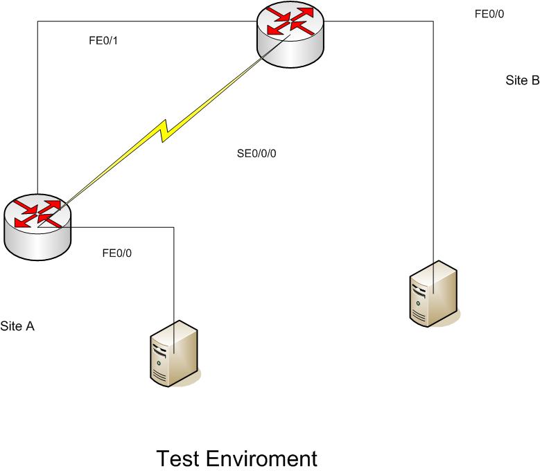
On my test setup the only thing I couldn't account for is the T1 line through Sprint (MPLS) which is transparent to us anyway. The firewalls which is where the VPN is initiated and terminated so I used a cross-over cable. Made the necessary ip changes to the test enviroment to allow connectivity. And a couple of test servers on each end to simulate traffic.
Here is the Basic setup for the test enviroment;
 -----------
By allowing EIGRP to determine routes I assume then I would need to define all attached network subnets under the EIGRP settings.
-----
ip route Site A
Gateway of last resort is 192.168.6.12 to network 0.0.0.0
D 192.168.24.0/24 [90/2693120] via 172.21.235.113, 1w0d, Serial0/0/0
172.21.0.0/30 is subnetted, 4 subnets
C 172.21.235.112 is directly connected, Serial0/0/0
D 172.21.235.116 [90/2690560] via 172.21.235.113, 1w0d, Serial0/0/0
D 172.21.235.120 [90/2690560] via 172.21.235.113, 7w0d, Serial0/0/0
D 172.21.235.148 [90/2690560] via 172.21.235.113, 5w6d, Serial0/0/0
S 172.20.0.0/16 [1/0] via 192.168.6.20
D 192.168.4.0/24 [90/2693120] via 172.21.235.113, 1w0d, Serial0/0/0
C 192.168.20.0/24 is directly connected, FastEthernet0/1
D 192.168.5.0/24 [90/2693120] via 172.21.235.113, 5w6d, Serial0/0/0
C 192.168.6.0/24 is directly connected, FastEthernet0/0
D 192.168.3.0/24 [90/2693120] via 172.21.235.113, 2w5d, Serial0/0/0
S* 0.0.0.0/0 [1/0] via 192.168.6.12
----------
ip route Site B
Gateway of last resort is 172.21.235.117 to network 0.0.0.0
C 192.168.24.0/24 is directly connected, FastEthernet0/1
172.21.0.0/30 is subnetted, 4 subnets
D 172.21.235.112 [90/2690560] via 172.21.235.117, 1w0d, Serial0/0/0
C 172.21.235.116 is directly connected, Serial0/0/0
D 172.21.235.120 [90/2690560] via 172.21.235.117, 1w0d, Serial0/0/0
D 172.21.235.148 [90/2690560] via 172.21.235.117, 1w0d, Serial0/0/0
D EX 172.20.0.0/16 [170/2693120] via 172.21.235.117, 1w0d, Serial0/0/0
C 192.168.4.0/24 is directly connected, FastEthernet0/0
D 192.168.20.0/24 [90/2693120] via 172.21.235.117, 1w0d, Serial0/0/0
D 192.168.5.0/24 [90/2693120] via 172.21.235.117, 1w0d, Serial0/0/0
D 192.168.3.0/24 [90/2693120] via 172.21.235.117, 1w0d, Serial0/0/0
S* 0.0.0.0/0 [1/0] via 172.21.235.117
--------------
On my test setup the only thing I couldn't account for is the T1 line through Sprint (MPLS) which is transparent to us anyway. The firewalls which is where the VPN is initiated and terminated so I used a cross-over cable. Made the necessary ip changes to the test enviroment to allow connectivity. And a couple of test servers on each end to simulate traffic.
Here is the Basic setup for the test enviroment;
-----------By allowing EIGRP to determine routes I assume then I would need to define all attached network subnets under the EIGRP settings.
Yes, that is how the network will converge either via the VPN or via the MPLS link.
The problem the Fe's should not be connected to the routers but to an external switch to mimic external connection, the serial connection between the routers can represent the MPLS link.
This way when you bring down the serial connection, the VPN should kick in for the purpose of routing between the devices on sitea and devices on siteb.
ASKER
Great. I didn't use the switch on the FE0/1 and used a cross cable. Same on the connections to the servers (cross).
So would I define all subnets on all routers? There's 4 involved.
In the test enviroment it does switch between the two router circuits but will always switch to the FE0/1 circuit if both are attached as that one is a faster link. That will be where I will use the delay metric to force to the T1. Again at this time I need to have the T1 as primary.
So in theory if I understand correctly the only place I would need a static route is on the Site A side to force the traffic destined for 172.20.0.0 to the 192.168.6.20 router and the routes that define the INET traffic? On all other routers I wouldn't need any route statements?
IN a way the test environment need only replicate the access to the single segment where the computer is represented.
A switch/cross that connects the Fe0/1 will mimic the cable connection.
The Serial0/0/0 connection will mimic the MPLS connection
The Fe0/0 will have their own lan/s. and the EIGRP between the two over the serial and over the VPN should provide a more realistic.
Presumably all traffic going to external resources should go over the Cable connection
ip route 0.0.0.0 0.0.0.0 fe0/1 on each of the test routers.
The EIGRP will deal with dynamically adding the routes of the LANs accessible behind them.
The only static route you will have is the default gateway by way of the cable for all traffic.
The VPN will define the interesting traffic that will be going through it.
The EIGRP will dynamically update the routing table on each router to direct traffic for those segments to the IP through the ATM or VPN.
Did you setup a VPN between the two routers in the test environment via the FE0/1 interface? You can not define a Route for the LAN traffic on the other router using the FE0/1 interface since this is not how your production environment is setup. Without the VPN, there is not path over the Fe0/1 interface to the LANs behind each router.
You can play/try with the delay setup in the test environment to see the threshold where the routing will start going th
ASKER
Hmmmm. triying to digest what you said.
"Presumably all traffic going to external resources should go over the Cable connection
ip route 0.0.0.0 0.0.0.0 fe0/1 on each of the test routers.
The EIGRP will deal with dynamically adding the routes of the LANs accessible behind them"
When you say external resources are you refering to INET traffic? If so then no all INET traffic goes thourgh the 192.168.6.12 route. And the main reason for this is our B2B relationships that require that they see a specific external IP address.
"Did you setup a VPN between the two routers in the test environment via the FE0/1 interface? You can not define a Route for the LAN traffic on the other router using the FE0/1 interface since this is not how your production environment is setup. Without the VPN, there is not path over the Fe0/1 interface to the LANs behind each router."
No there isn't a VPN on the test enviroment as that is being handled by other equipment. I modified the IP addresses on the test enviroment to allow connection. VPN connection appears to be still a problem and I'm working on that issue. In the test enviroment I can see and access all servers using either the SE0/0/0 link or the FE0/1 link.
So if I understand correctly I do not need any ip route statements on any router EXCEPT site A because of the directed traffic to the INET and our data host router.
I do apologize I'm having a difficult time getting a handle on what's needed. Also you mentioned about "auto-summary" Could you elaborate a bit more and would changeing this setting affect how EIGRP operates?
Misread your application, the no auto-summary should remain in place.
In the absence of a firewall equipment, you should setup the Cisco VPN and see whether you can configure Routing protocol over the VPN connection as well.
You have to have a route that in the event the MPLS goes down, there is a path to the outside.
I think this is what you were working on with EIGRP and the dealy.
i.e. ip route 0.0.0.0 0.0.0.0 fe0/1 100
The other issue is that to insure that VPN connections go over the cable connection, you would need to add static routes to avoid having the VPN connection going over the MPLS to site A and exit site A to get to Site C to establish a VPN.
ASKER
OK, keep auto-summary..
FE0/1 connects to a firewall that also performs the VPN duties. Router IOS does not have the VPN feature set.
OK, so I do need the route statements. Now do I need them on both ends? i.e. A ->B and B->A and if so then for my configuration it would have one for A->B, A->C, A->D for Site A and B->A (site B), C->A (site C), D->A (site D). This is where I'm having the most confusion. And the "100" after the ip route is that for delay?
VPN doesn't have a choice about going over the cable connection as the real world connection is <router> -> <firewall/vpn> -> <cable modem>
Now I also am making an guess that under EIGRP there would be a network entry for each of the FE0/1(s) on each router (192.168.20.0, .23.0, .24.0, .25.0)
Again Thanks, hopefully I'm getting a handle on this. The last time I tried to apply some of this I lost partial connection with site B (surprised I didn't lose all connection).
keep (no auto-summary) since auto-summary will aggregate segments into a larger single segment which you do not want.
I do not think you need to define static routes since you are relying on dynamic updates of the routing table.
What you can do is push the external IP through which all traffic must come from Site A, through EIGRP.
i.e. if access to site of company XYZ must be sent via the VPN or via MPLS to site A and exit that way, and company be has a Public Range: x.y.z.0/24 you can add the x.y.z.0 network to the EIGRP configuration advertised from SiteA to all.
This way you can send non-relavent Internet traffic through the cable connection while assuring the specific traffic exits through site A. The only issue is that you would need to setup some monitoring to make sure that company XYZ when it expands and gets additional IP ranges, does not switch the site you currently access on x.y.z.w to a new segment.
With the current requirement, your VPN will have to be the secureall type to assure that should the MPLS link fail, all traffic is sent through the VPN to site A to handle the issue with the single source to a specific site.
ASKER
OK, a bit more detail on static routes that will or won't be needed please. It seems we're going back and forth on whether I need to define routes at each location or is EIGRP going to figure them out.
Unfortunately I didn't understand what you meant about pushing external IP.
For our monitoring requirements all INET traffic must go through Site A.
All B2B connects to our main INET Firewall at Site A. Only exception is our data host which has their own router 6.20.
Unfortunately I didn't understand what you meant about pushing external IP.
For our monitoring requirements all INET traffic must go through Site A.
All B2B connects to our main INET Firewall at Site A. Only exception is our data host which has their own router 6.20.
EIGRP will converge the internal plus the specific provider you have that must originate through the Site A's connection.
All static routes
ip route 0.0.0.0 0.0.0.0 Fe<> 10 should point to the cable feed with a lower weight
and you probably should include the failover for all network traffic to go via the MPLS in the event the cable feed goes down by using a higher weight
ip route 0.0.0.0 0.0.0.0 MPLS_link 100
relooking at your requirement that all traffic must go to site A, that makes the issue more complicated since the VPN is establish on an upstream device on the cable feed.
So this will change:
#preferred
ip route 0.0.0.0 0.0.0.0 MPLS_link 10
#failover cable where the VPN setup is to secure all networks This can be done by configuring the VPN to have a routing protocol i.e. ospf and pushing from site a that all traffic should be sent its way.
ip route 0.0.0.0 0.0.0.0 FE<> 50
ASKER
OK, I will try these settings out on the test enviroment and get back with you. Will probably be next week before I can accomplish this.
TIA
TIA
ASKER
Back in the saddle again, want to verify some changes first. From our previous conversations I've gathered that on all routers that under the EIGRP settings I need to have ALL subnets that are connected to the routers. This would look like on the Site A router;
router eigrp 100
redistribute static
network 172.21.0.0 <-B2B
network 192.168.6.0 <-local subnet
network 192.168.20.0 <-FE0/1 "Test enviroment site A"
network 192.168.23.0 <-Site C
network 192.168.24.0 <-Site B "Test enviroment Site B"
network 192.168.25.0 <-Site D
no auto-summary
----------------
Site B router
router eigrp 100
redistribute connected
network 172.21.0.0
network 192.168.4.0 <-local subnet
network 192.168.20.0 <-Site A "Test Site A"
network 192.168.23.0 <-Site C
network 192.168.24.0 <-FE0/1
network 192.168.25.0 <-Site D
no auto-summary
-------------------------
Site C and Site D routers set appropriately.
And also assuming connectiviity with the VPN/Firewall appliance hanging off of the FE0/1 interface EIGRP should be able to know all routes and be able to connect either by SE0/0/0 (T1) or the VPN.
Does this appear correct?
Thanks.
router eigrp 100
redistribute static
network 172.21.0.0 <-B2B
network 192.168.6.0 <-local subnet
network 192.168.20.0 <-FE0/1 "Test enviroment site A"
network 192.168.23.0 <-Site C
network 192.168.24.0 <-Site B "Test enviroment Site B"
network 192.168.25.0 <-Site D
no auto-summary
----------------
Site B router
router eigrp 100
redistribute connected
network 172.21.0.0
network 192.168.4.0 <-local subnet
network 192.168.20.0 <-Site A "Test Site A"
network 192.168.23.0 <-Site C
network 192.168.24.0 <-FE0/1
network 192.168.25.0 <-Site D
no auto-summary
-------------------------
Site C and Site D routers set appropriately.
And also assuming connectiviity with the VPN/Firewall appliance hanging off of the FE0/1 interface EIGRP should be able to know all routes and be able to connect either by SE0/0/0 (T1) or the VPN.
Does this appear correct?
Thanks.
The EIGRP should only advertise the networks that it has.
I..e site A will only advertise its Directly connected networks.
I'm not sure where the interconnecting 172.21.0.0 needs to be advertised.
Site B router
router eigrp 100
redistribute connected
network 172.21.0.0 ??????
network 192.168.4.0 <-local subnet
network 192.168.24.0 <-FE0/1
no auto-summary
The EIGRP will not play a role in the VPN
The VPN since all traffic must flow through to Site A, should be configured in such a way.
You may have to configure the Firewall as a remote client VPN with secureall networks as the option. (no split tunneling)
In this configuration, it will not matter whether the traffic goes over the MPLS or the VPN since it will/should wind up on site A. You would need to configure the firewall on site A that deals with NAT same-security-traffic permit inter-interface same-security-traffic permit intra-interface
I think there is also the sysopt permit-ipsec sysopt permit-vpn
Do you need intersite Site B to Site C communicaitons?
ASKER
OK, so as an example Site A should only have
router eigrp 100
redistribute static
network 172.21.0.0 <-SE0/0/0 "relooked on my configuration"
network 192.168.6.0 <-local subnet
network 192.168.20.0 <-FE0/1 "Test enviroment site A"
no auto-summary
.......And this is what the original configuration has.
----------------
Site B router has and possible change?
router eigrp 100
redistribute connected
network 172.21.0.0
network 192.168.4.0 <-local subnet
network 192.168.20.0 <-Site A "Test Site A". "Maybe should be 192.168.24.0?"
no auto-summary
....This is the original configuration but what you're saying the 192.168.20.0 should be changed to 192.168.24.0 as that is the directly connected FE0/1.
The 172.21.0.0 are on all the routers and they connect to the SE0/0/0 interface "T1"
router eigrp 100
redistribute static
network 172.21.0.0 <-SE0/0/0 "relooked on my configuration"
network 192.168.6.0 <-local subnet
network 192.168.20.0 <-FE0/1 "Test enviroment site A"
no auto-summary
.......And this is what the original configuration has.
----------------
Site B router has and possible change?
router eigrp 100
redistribute connected
network 172.21.0.0
network 192.168.4.0 <-local subnet
network 192.168.20.0 <-Site A "Test Site A". "Maybe should be 192.168.24.0?"
no auto-summary
....This is the original configuration but what you're saying the 192.168.20.0 should be changed to 192.168.24.0 as that is the directly connected FE0/1.
The 172.21.0.0 are on all the routers and they connect to the SE0/0/0 interface "T1"
ASKER
Just looked at our production routers. Site be does indeed have 192.168.24.0 instead of 192.168.20.0. Looks like I need to update my backup routers.
This is routing advertising protocol. When these packets are received the routing table gets updated with the neighbor through which a network is accessible.
Do you need site B to site C communication via MPLS or VPN?
Do you need site B to site C communication via MPLS or VPN?
ASKER
Eventually will update to provide additional routes but for now no. The important routes is to get from Site B,C,D back to A. Anything else is icing on the cake.
With this setup, each site should now reflect dynaimc paths to A.
IN your test setup, if you add the network 0.0.0.0 to the eigrp configuration on the "A" router that should add the dynamic path on the peers through A.
Are you at this time also working on the VPN between each site and SIte A?
IN your test setup, if you add the network 0.0.0.0 to the eigrp configuration on the "A" router that should add the dynamic path on the peers through A.
Are you at this time also working on the VPN between each site and SIte A?
ASKER
So under EIGRP add a "network 0.0.0.0"?
Yes, According to documentation and the company it should work. What the vendor is telling me is that the VPN will be created upon receiving some traffic on the internal interface and once receive will create a permenant VPN connection. I believe that the routers will transmit some kind of keep-alive packet and or a route discovery packet on the FE0/1 interface and that will initiate the VPN connection.
Yes, According to documentation and the company it should work. What the vendor is telling me is that the VPN will be created upon receiving some traffic on the internal interface and once receive will create a permenant VPN connection. I believe that the routers will transmit some kind of keep-alive packet and or a route discovery packet on the FE0/1 interface and that will initiate the VPN connection.
ASKER CERTIFIED SOLUTION
membership
This solution is only available to members.
To access this solution, you must be a member of Experts Exchange.
ASKER
Yes VPN will only occur upon MPLS failure (at this time).
These are static VPN tunnels Point A to Point B type.
OK will leave the network 0.0.0.0 out but will test as best as I can.
These are static VPN tunnels Point A to Point B type.
OK will leave the network 0.0.0.0 out but will test as best as I can.
ASKER
arnold, thank you so very much for your help. At this time my routing seems to be correct and after I resolve my firewall issue I should be in business. But that's for another forum. You're configuration examples and explainations were spot on even though I had a hard time understanding. Turns out the routers are already configured correctly except for a static route which I will remove from the rest of the routers (already removed from one remote without ill effects on traffic). Thank you again.
Richard
Richard
The problem that I am not seeing is whether your firewall has both the cisco router and the cable connection drop on it.
To control failover, you have to have a single device that is the choke point for the traffic such that rules on this device will govern how and by what path a packet will travel.
Your main office has a firewall into which the cable modem plugs in and into which the cisco router and the LAN computers are plugged in,
cable \
firewall (MPLS seen as trusted) <=> LAN
MPLS/
with OSPF and VPN on the cable connection with the cost of OSPF over VPN being higher as long as the MPLS connection is up traffic to the other LANs will flow through the MPLS link. When this link drops, the traffic will converge to go through the Cable VPN.