How to optimize my notch filter ?
Hello Guys,
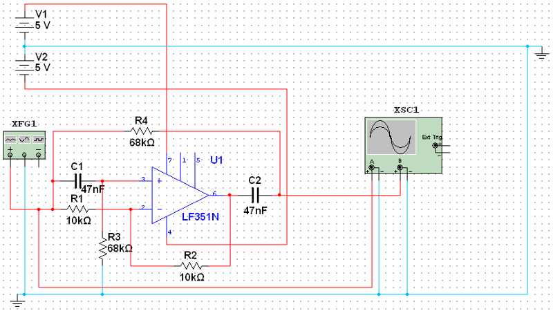
I need to design and build a notch filter to remove the 50 Hz main electricity before outputting my ECG (ElectroCardioGraphy signal) on an oscilloscope.
I used this source to build one http://www.radio-electronics.com/info/circuits/opamp_notch_filter/opamp_notch_filter.php
I'm using the LF351 op-amp because it's got high noise impedance (am I right in that ?)
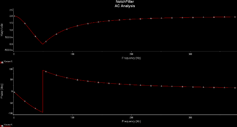
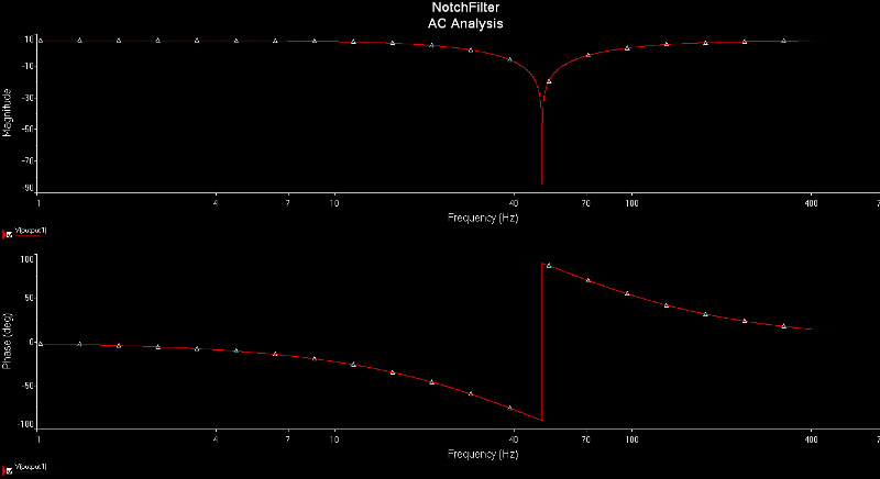
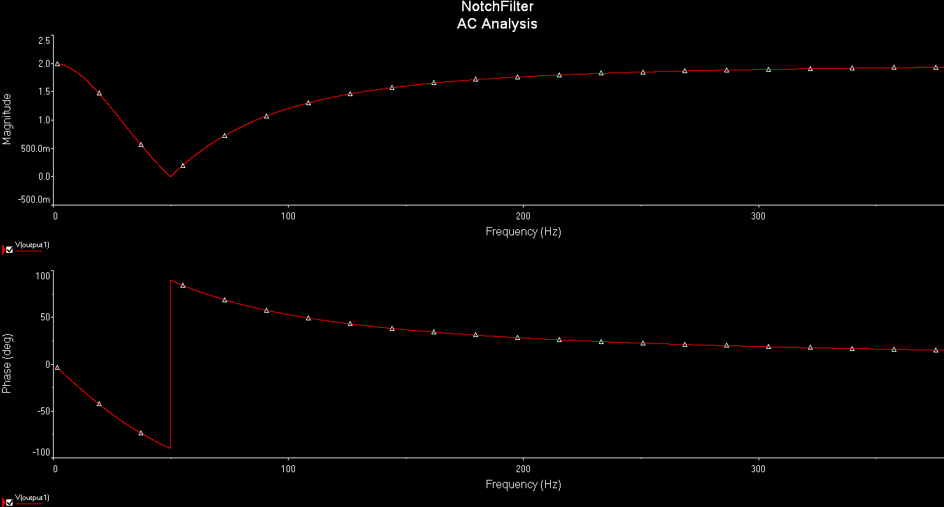
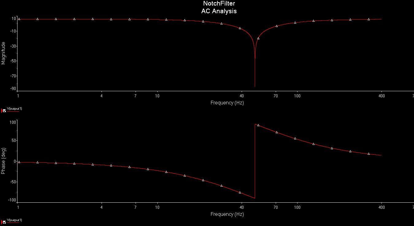
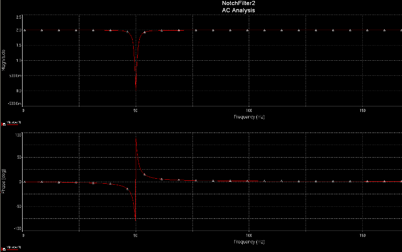
I've attached screenshots of my circuit, and a bode plot and all. Please have a look at them.
The question is, how can I optimize my notch filter ? how can I make signals of 40 and 60 less attenuated (since I only want 50 to be attenuated to zero) ? How can I make it more accurate basically ? Please feel free to suggest :D
I need to design and build a notch filter to remove the 50 Hz main electricity before outputting my ECG (ElectroCardioGraphy signal) on an oscilloscope.
I used this source to build one http://www.radio-electronics.com/info/circuits/opamp_notch_filter/opamp_notch_filter.php
I'm using the LF351 op-amp because it's got high noise impedance (am I right in that ?)
I've attached screenshots of my circuit, and a bode plot and all. Please have a look at them.
The question is, how can I optimize my notch filter ? how can I make signals of 40 and 60 less attenuated (since I only want 50 to be attenuated to zero) ? How can I make it more accurate basically ? Please feel free to suggest :D
ASKER CERTIFIED SOLUTION
membership
This solution is only available to members.
To access this solution, you must be a member of Experts Exchange.
d-glitch
>> The adjustable Q might help.
SOLUTION
membership
This solution is only available to members.
To access this solution, you must be a member of Experts Exchange.
SOLUTION
membership
This solution is only available to members.
To access this solution, you must be a member of Experts Exchange.
ASKER
@d-glitch
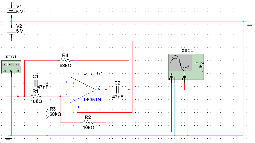
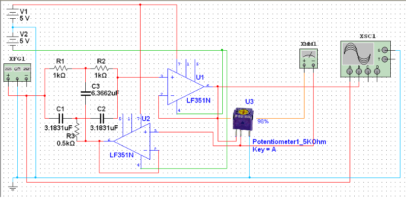
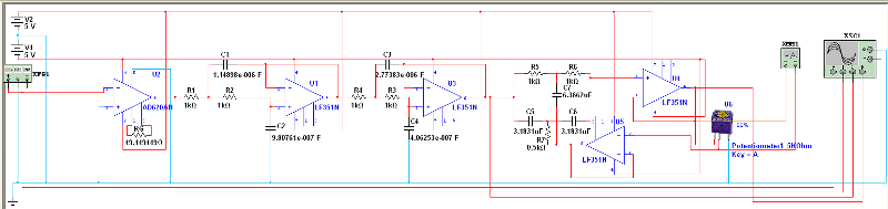
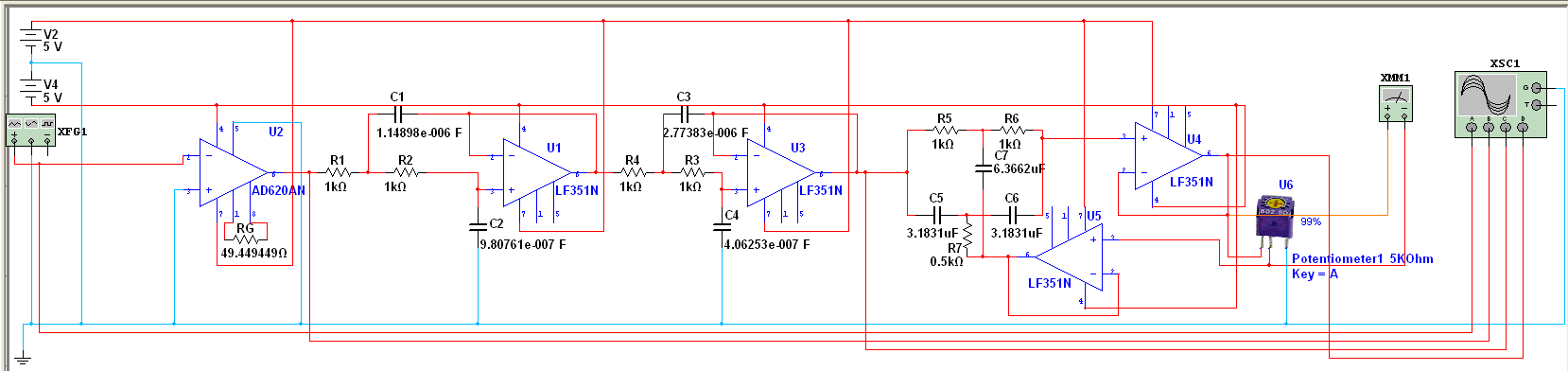
Thanks so much for your help so far. I did simulate the 2nd diagram and it gave me a much much better bode plot, I've attached the circuit diagram and outputs here.
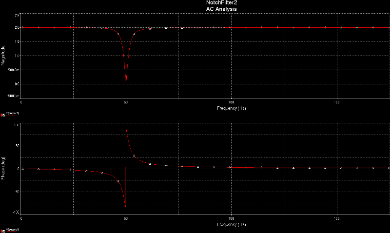
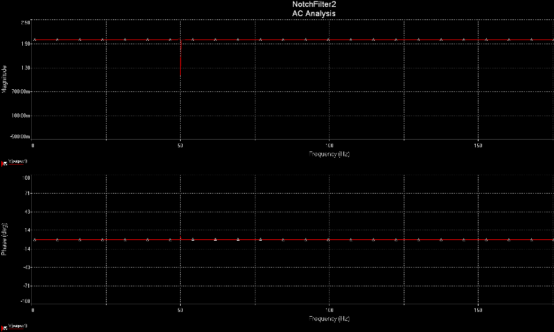
Question is, what range should the potentiometer be within ? the simple requirement is to remove noise from the mains electricity and keep the rest of the signal untouched. I'm still gonna do an FFT, but for the time being, I simulated with Q = 98, Q = 99 and Q = 100 and I've attached the 3 responses here. 99% seems the best, and 50 Hz does go down to zero, but there is a major problem, when my signal generator inputs 100 Hz for example, then I change the input to 50 Hz, it takes a lot of time to go down to zero, and if I then change it to 100 Hz, it still takes a lot of time to go back to full gain. anything I can change to keep that need bode plot but have a much much faster reponse to change in signal ? Will it actually affect me, i.e in simulation I change the signal from 50 Hz to 100 Hz, but in reality, both frequencies will be present in the same signal, will the slow response affect me in reality ?
@DaveBaldwin
Thanks so much for your amazing tips and suggestions. Don Loncaster's "Active Filter Cookbook" is a great book by the way. Could you please explain why the signal output should be take from pin 6 and not after the resistor/capacitor junction ? I will have to take the output from the resistor/capacitor junction to input it to another filter maybe, so I might as well connect the oscilloscope to that output not to pin 6, did you understand what I want to tell you ? Also please explain what you meant by "Precision parts will help it work better too" ??? are you talking about the potentiometer ?
@viki2000
Thanks so much for your wonderful links, I am using MultiSim already, it'll take me some time to check your links, in the mean time if you have any suggestions please do suggest.
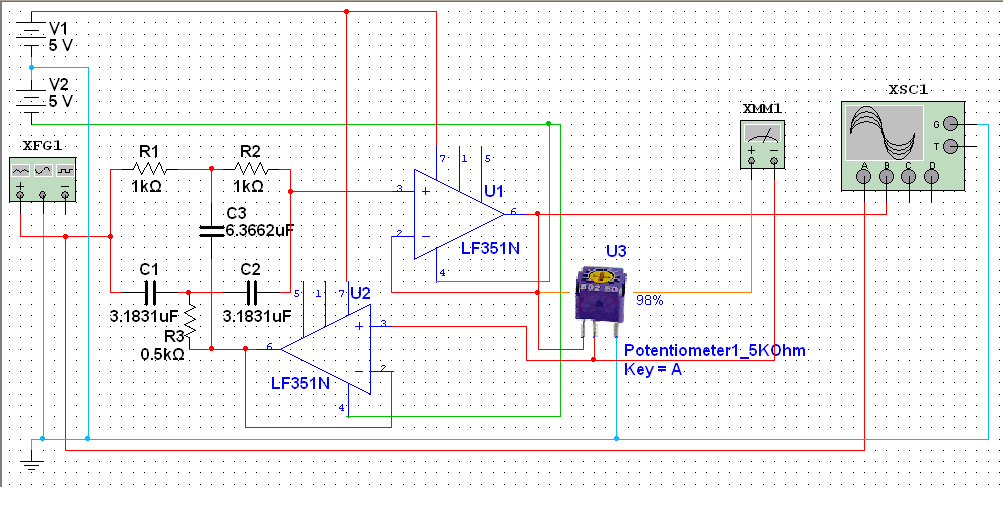
My final circuit looks as follows (again the problem is the notch filter has a very slow response):
Please Help, thank you
Thanks so much for your help so far. I did simulate the 2nd diagram and it gave me a much much better bode plot, I've attached the circuit diagram and outputs here.
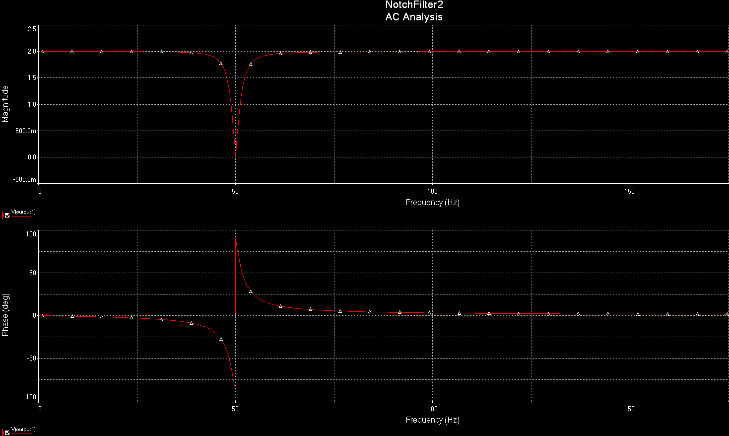

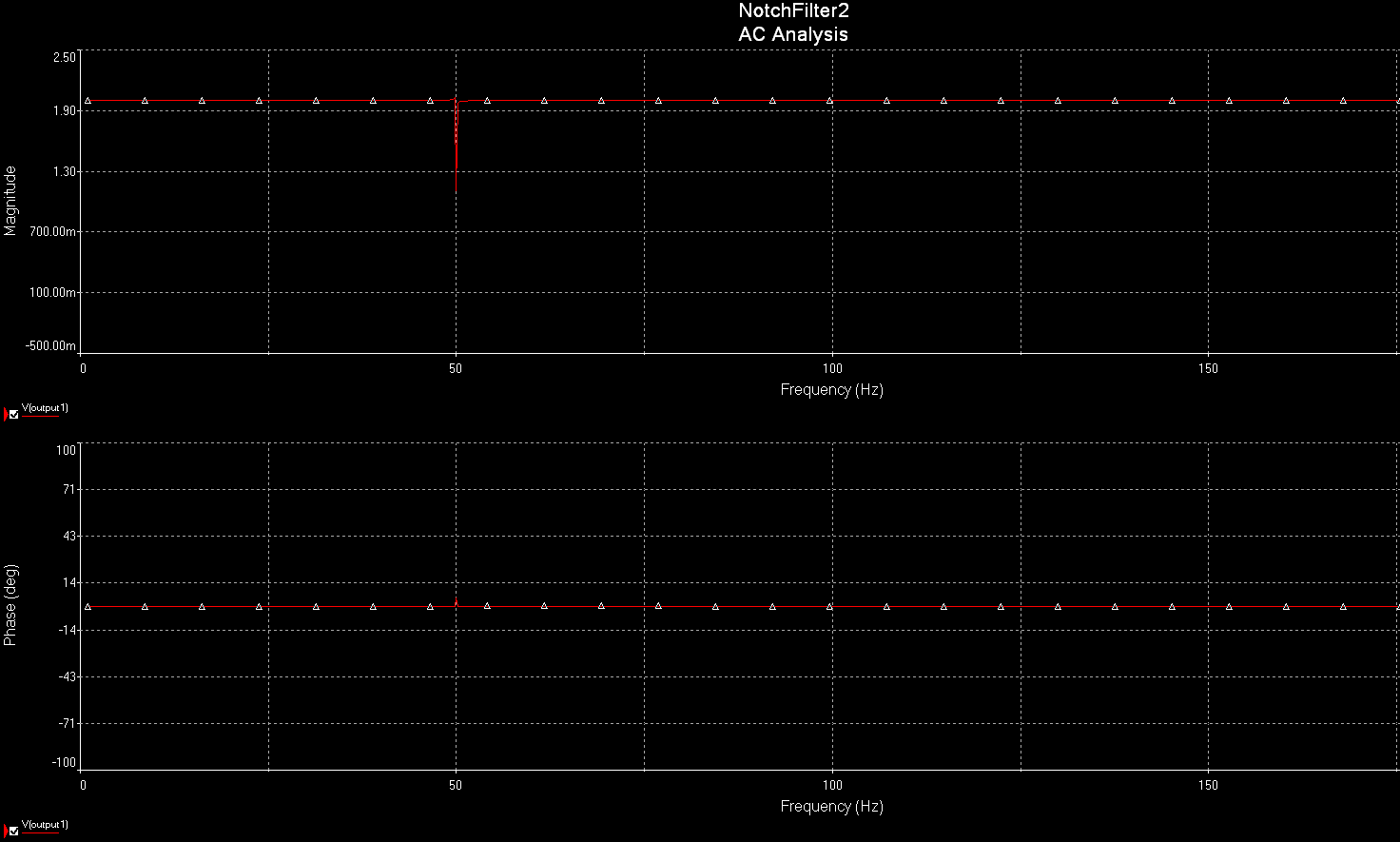
Question is, what range should the potentiometer be within ? the simple requirement is to remove noise from the mains electricity and keep the rest of the signal untouched. I'm still gonna do an FFT, but for the time being, I simulated with Q = 98, Q = 99 and Q = 100 and I've attached the 3 responses here. 99% seems the best, and 50 Hz does go down to zero, but there is a major problem, when my signal generator inputs 100 Hz for example, then I change the input to 50 Hz, it takes a lot of time to go down to zero, and if I then change it to 100 Hz, it still takes a lot of time to go back to full gain. anything I can change to keep that need bode plot but have a much much faster reponse to change in signal ? Will it actually affect me, i.e in simulation I change the signal from 50 Hz to 100 Hz, but in reality, both frequencies will be present in the same signal, will the slow response affect me in reality ?
@DaveBaldwin
Thanks so much for your amazing tips and suggestions. Don Loncaster's "Active Filter Cookbook" is a great book by the way. Could you please explain why the signal output should be take from pin 6 and not after the resistor/capacitor junction ? I will have to take the output from the resistor/capacitor junction to input it to another filter maybe, so I might as well connect the oscilloscope to that output not to pin 6, did you understand what I want to tell you ? Also please explain what you meant by "Precision parts will help it work better too" ??? are you talking about the potentiometer ?
@viki2000
Thanks so much for your wonderful links, I am using MultiSim already, it'll take me some time to check your links, in the mean time if you have any suggestions please do suggest.
My final circuit looks as follows (again the problem is the notch filter has a very slow response):
Please Help, thank you
SOLUTION
membership
This solution is only available to members.
To access this solution, you must be a member of Experts Exchange.
SOLUTION
membership
This solution is only available to members.
To access this solution, you must be a member of Experts Exchange.
ASKER
d-glitch, DaveBaldwin, and viki2000
Can you guys have a look at my new question please ?
https://www.experts-exchange.com/questions/27455912/How-to-find-the-frequencies-present-in-a-signal-for-ElectroCardiography-application-How-to-do-FFT.html
Can you guys have a look at my new question please ?
https://www.experts-exchange.com/questions/27455912/How-to-find-the-frequencies-present-in-a-signal-for-ElectroCardiography-application-How-to-do-FFT.html