Why Can't I Ping?
Ok. I would like to know why I can't ping some of the nodes on my network. I use a CISCO 3750G as a CORE SWITCH with 6 seperate LANs. 4 of the six use 3750G switches and the other 2 use 2950G switches. Now, I can ping the 2950's and 1 of the 3750's but that's it. I have attached the configuration files of the CORE Switch, one 3750 that I can ping and one that I can't. I have also included the router configs for each.
270-ENG-12-26-12.TXT
270-TEST-12-26-12.TXT
Core-Switch-12-26-12.TXT
ENG-Router-12-26-12.TXT
Land-Router-12-26-12.TXT
TEST-Router-12-26-12.TXT
270-ENG-12-26-12.TXT
270-TEST-12-26-12.TXT
Core-Switch-12-26-12.TXT
ENG-Router-12-26-12.TXT
Land-Router-12-26-12.TXT
TEST-Router-12-26-12.TXT
for core, ping the gateway, not the individual device
ASKER
@rauenpc- Remember, I have 6 seperate LAN's. They are not mismatches there are 6 seperate IP addresses. 192.168.100.0, 192.168.78.0, 192.168.70.0, 192.168.200.0, 192.168.170.0, and 192.168.178.0.
If you are trying to configure intervlan routing, each Vlan interface at the core needs an ip address.
The VLAN's need to be tagged for all of them to be able to ping each other. VLAN's only go through trunked ports.
Run the following commands
On the core switch and paste a scrambled output
Show CDP neighbors
Show ip interfaces brief
Show VLAN
Show VTP
Let's start with theses three
On the core switch and paste a scrambled output
Show CDP neighbors
Show ip interfaces brief
Show VLAN
Show VTP
Let's start with theses three
I meant
Show VTP status
Show VTP status
Is IP route enabled on the 3750
ASKER
Yes, IP Route is enabled.
ok
run the test commands above to see why the routes are not traversing.
run the test commands above to see why the routes are not traversing.
ASKER
SH CDP NEI-
Capability Codes: R - Router, T - Trans Bridge, B - Source Route Bridge
S - Switch, H - Host, I - IGMP, r - Repeater, P - Phone,
D - Remote, C - CVTA, M - Two-port Mac Relay
Device ID Local Intrfce Holdtme Capability Platform Port ID
SEAWATCH_TEST_ROUTER
Gig 1/0/12 127 R S I 2811 Fas 0/0
SEAWATCH_LANDBASE_ROUTER
Gig 1/0/23 146 R S I 2811 Fas 0/0
LAB_FRC_ENG.uscg.smil.mil
Gig 1/0/1 177 S I WS-C2960G Gig 0/7
LAB_FRC_TEST Gig 1/0/2 160 S I WS-C2960G Gig 0/7
LAB_270_ENG Gig 1/0/5 120 S I WS-C3750G Gig 1/0/24
LAB_378_ENG Gig 1/0/3 179 S I WS-C3750G Gig 1/0/24
SEAWATCH_ENG_ROUTER
Gig 1/0/11 146 R S I 2811 Fas 0/0
Lab_378_TEST Gig 1/0/4 179 S I WS-C3750G Gig 1/0/24
LAB_270_TEST Gig 1/0/6 164 S I WS-C3750G Gig 1/0/24
LAND_SWITCH2 Gig 1/0/14 148 R S I WS-C3750G Gig 1/0/31
LAND_SWITCH2 Gig 1/0/13 148 R S I WS-C3750G Gig 1/0/15
SH VLAN-
VLAN Name Status Ports
---- --------------------------
1 default active Gi1/0/7, Gi1/0/8, Gi1/0/9
Gi1/0/10, Gi1/0/17, Gi1/0/18
Gi1/0/19, Gi1/0/20, Gi1/0/21
Gi1/0/22
2 FRC_ENG_SEAWATCH active
3 378_ENG_SEAWATCH active Gi1/0/1, Gi1/0/15
4 FRC_TEST_SEAWATCH active Gi1/0/2, Gi1/0/16
5 378_TEST_SEAWATCH active Gi1/0/4
6 SEAWATCH_172.16.100.0 active Gi1/0/3, Gi1/0/13
7 SEAWATCH_172.16.200.0 active Gi1/0/14
8 270_ENG_SEAWATCH active Gi1/0/5
9 270_TEST_SEAWATCH active Gi1/0/6
10 VLAN0010 active
11 test active
12 VLAN0012 active
16 VLAN0016 active
22 VLAN0022 active
1002 fddi-default act/unsup
1003 token-ring-default act/unsup
1004 fddinet-default act/unsup
VLAN Name Status Ports
---- --------------------------
1005 trnet-default act/unsup
VLAN Type SAID MTU Parent RingNo BridgeNo Stp BrdgMode Trans1 Trans2
---- ----- ---------- ----- ------ ------ -------- ---- -------- ------ ------
1 enet 100001 1500 - - - - - 0 0
2 enet 100002 1500 - - - - - 0 0
3 enet 100003 1500 - - - - - 0 0
4 enet 100004 1500 - - - - - 0 0
5 enet 100005 1500 - - - - - 0 0
6 enet 100006 1500 - - - - - 0 0
7 enet 100007 1500 - - - - - 0 0
8 enet 100008 1500 - - - - - 0 0
9 enet 100009 1500 - - - - - 0 0
10 enet 100010 1500 - - - - - 0 0
11 enet 100011 1500 - - - - - 0 0
12 enet 100012 1500 - - - - - 0 0
16 enet 100016 1500 - - - - - 0 0
22 enet 100022 1500 - - - - - 0 0
1002 fddi 101002 1500 - - - - - 0 0
1003 tr 101003 1500 - - - - srb 0 0
1004 fdnet 101004 1500 - - - ieee - 0 0
1005 trnet 101005 1500 - - - ibm - 0 0
Remote SPAN VLANs
--------------------------
Primary Secondary Type Ports
------- --------- ----------------- --------------------------
SH VTP INT
Interface VTP Status
--------------------------
GigabitEthernet1/0/1 enabled
GigabitEthernet1/0/2 enabled
GigabitEthernet1/0/3 enabled
GigabitEthernet1/0/4 enabled
GigabitEthernet1/0/5 enabled
GigabitEthernet1/0/6 enabled
GigabitEthernet1/0/7 enabled
GigabitEthernet1/0/8 enabled
GigabitEthernet1/0/9 enabled
GigabitEthernet1/0/10 enabled
GigabitEthernet1/0/11 enabled
GigabitEthernet1/0/12 enabled
GigabitEthernet1/0/13 enabled
GigabitEthernet1/0/14 enabled
GigabitEthernet1/0/15 enabled
GigabitEthernet1/0/16 enabled
GigabitEthernet1/0/17 enabled
GigabitEthernet1/0/18 enabled
GigabitEthernet1/0/19 enabled
GigabitEthernet1/0/20 enabled
Interface VTP Status
--------------------------
GigabitEthernet1/0/21 enabled
GigabitEthernet1/0/22 enabled
GigabitEthernet1/0/23 enabled
GigabitEthernet1/0/24 enabled
I have to go back to the lan to do the sh ip int brief.
You ran "show vtp int" instead of "show vtp status"
Also, please provide a simple diagram. I was going to create a diagram for it to see how they are connected.
I will check it out later in the evening (PT).
Also, please provide a simple diagram. I was going to create a diagram for it to see how they are connected.
I will check it out later in the evening (PT).
ASKER
Ok. I figured it out with your suggestion of IP Routing. It was off on the LAN I could ping and on on the others. Once I turned it off, I can ping each LAN from each other. However, I still cannot ping ANYTHING on or from the core switch.
ASKER
Any thoughts on the core switch issue? I am assuming I need to have an IP to ping and respond to pings, but I can't assign it anything other than an IP address pool.
I will take a deep look at the configuration and get back to you. I was very busy yesterday and today despite being under the weather. Do you have a brief diagram as to how these units are connected - it will save me some time finding the bottleneck
Thx
Thx
ASKER
Drawing1.vst The diagram you pointed me to has no information that I need.
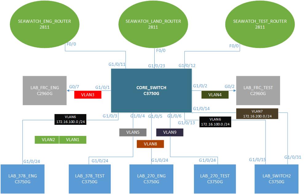
I made a simple diagram based on the information I found. See attached
I noticed that the switchports connecting to other switches on the Core switch are set to access mode (They should be trunk ports connected with a crossover cable. They shouldn't be assigned to a vlan either. You would assign vlans to access switches)
Review Cisco's 3-Layered Hierarchical Model (Access Layer, Distribution Layer and Core Layer)
You didn't give me the VTP status info to see if vlans created on the core switch (which I recommend should be the only VTP server) is replicated to the other switches.
I also noticed that there are 2 connections to Land switch 2 via port 13 and 14 - Initially I thought you created an etherchannel but saw that the ports are access ports two which makes etherchannel impossible on those links.
 The diagram you pointed me to has no information that I need.
I made a simple diagram based on the information I found. See attached
I noticed that the switchports connecting to other switches on the Core switch are set to access mode (They should be trunk ports connected with a crossover cable. They shouldn't be assigned to a vlan either. You would assign vlans to access switches)
Review Cisco's 3-Layered Hierarchical Model (Access Layer, Distribution Layer and Core Layer)
You didn't give me the VTP status info to see if vlans created on the core switch (which I recommend should be the only VTP server) is replicated to the other switches.
I also noticed that there are 2 connections to Land switch 2 via port 13 and 14 - Initially I thought you created an etherchannel but saw that the ports are access ports two which makes etherchannel impossible on those links.
ASKER
SH VTP STATUS:
VTP Version Capable : 1 to 3
VTP Version Running : 1
VTP Domain Name : NEWPALM
VTP Pruning Mode : Disabled
VTP Traps Generation : Disabled
Device ID : 0013.193e.1880
Configuration last modified by 10.100.10.1 at 3-13-93 10:27:54.
Local updater ID is 0.0.0.0 (no valid interface found)
Feature VLAN
-------------------
VTP Operating Mode :Server
Maximum VLANS supported locally: 1005
Number of existing VLANs : 18
Configuration Rvision : 117
MD5 Digest : Blah blah blah...
Did you change the port settings to trunk?
Check the VTP status on the other switches to see if VLAN information is replicated to them (you don't have to post the results)
Check the VTP status on the other switches to see if VLAN information is replicated to them (you don't have to post the results)
ASKER
It is not replicated to all switches. I have not set the ports to trunk yet. I am assuming that the new port settings will look like this...?
interface GigabitEthernet0/3
description 270_Engineering_LAN
switchport trunk encapsulation dot1q
switchport mode trunk
How does this affect the other end? It currently looks like this...
interface FastEthernet0/0.8
description 270 Engineering Router Interface
encapsulation dot1Q 8
ip address 192.168.70.254 255.255.255.0
ip flow ingress
ip flow egress
ASKER CERTIFIED SOLUTION
membership
This solution is only available to members.
To access this solution, you must be a member of Experts Exchange.
ASKER
So on the LAN Switch
int gi1/0/24
description bl;ah blah blah
switchport trunk encapsulation dot1q
switchport mode trunk
On the core
interface GigabitEthernet1/0/5
description 270_Engineering_LAN
switchport trunk encapsulation dot1q
switchport mode trunk
And on the router...
interface FastEthernet0/0.8
description 270 Engineering Router Interface
encapsulation dot1Q 8
ip address 192.168.70.254 255.255.255.0
ip flow ingress
ip flow egress
Correct!
The port on the Core_Switch (G1/0/11) that connects to F0/0 on the Seawatch_Eng_Router must also be a trunk port.
interface GigabitEthernet1/0/11
description 270_Engineering_LAN
switchport trunk encapsulation dot1q
switchport mode trunk
The port on the Core_Switch (G1/0/11) that connects to F0/0 on the Seawatch_Eng_Router must also be a trunk port.
interface GigabitEthernet1/0/11
description 270_Engineering_LAN
switchport trunk encapsulation dot1q
switchport mode trunk
ASKER
Ok. I will give it a shot after the new year.
ASKER
Ok...I failed appearently. This is what I tried.
On the local LAN...(This is a 2960 BTW...)
int gi0/7
description FRC_ENG
Switchport trunk native vlan 3
switchport mode trunk
vlan 3
no ip address
On the Core Switch...(3750G)
int gi1/0/1
description FRC_ENG
switchport encapsulation dot1q
switchport mode trunk
(I also tried with switchport trunk native vlan 3)
vlan 3
no ip address
On the ENG Router (2811)
int fa0/0.3
description FRC_ENG_INTERFACE
encapsulation dot1q 3
ip address 192.168.100.3 255.255.255.192
This did not work. What am I missing?
Native vlan is for untagged packets. Traffic from any device not tagged on the switchport is assigned to whatever vlan you identify as native.
You must have your native vlans the same throughout your network or you'll get native vlan mismatch messages - which results in bridged vlans.
I think I understand what you are trying to do.
Looks like you want to have a management vlan.
That is a completely different setup.
The currect setup is to segment you network into multiple vlans and control how traffic traverses within. To manage your switches you will have to put the switch in a management vlan, let's assume you chose 3 as your managment vlan.
On every switch, you would configure the following
Switch(config)# interface vlan 3
Switch(config-int)# ip address 192.168.100.x 255.255.255.192
Switch(config)# ip default-gateway 192.168.100.3
ASKER
No. In our field environment, we assign a port to native vlan 7 and set the port to trunk.
Specifically,
int gi0/7
switchport trunk native vlan 7
switchport mode trunk
I do not know what is on the other side of the switch in the field. However, I do know what my lab setup is. Their is no other changes made to the LAN switch other than setting the trunk to native valn 7. From the LAN switch, it goes to another switch that I do not have access to, after that, I do not know where it goes. I assume to a border router somewhere.
Read up of Native Vlan and Native Vlan Mismatch
Example
Switch A = Native Vlan 7
Switch B = Native Vlan 3
You will see a lot of native vlan mismatches on your debug output.
The result of this is, broadcast messages sent from untagged packets from switch A (vlan 7) will appear in switch B (vlan 3) because both networks are now bridged together. That defeats the purpose of vlan in the first place because one of the main reasons you create vlans is to separate networks into multiple broadcast domains, etc.
ASKER
So bottom line is I need to know how the other side of the field environment is set up to avoid the mismatch errors.
ASKER
Thanks for all your help. I did not fix the issue yet, but I am on the right path.
Absolutely.
A strong network is built layer by layer (OSI model).
Layer 1, involves correct cabling etc
Layer 2, involves appropriate port configurations and assignment.
In your case, we're dealing with Layer 2 issues
You are definitely on the right path -
All the best
A strong network is built layer by layer (OSI model).
Layer 1, involves correct cabling etc
Layer 2, involves appropriate port configurations and assignment.
In your case, we're dealing with Layer 2 issues
You are definitely on the right path -
All the best
interface Vlan10
description CORE_VLAN
ip address 192.168.70.1 255.255.255.0
no ip route-cache cef
no ip route-cache
no ip mroute-cache
!
270-TEST
interface Vlan10
ip address 192.168.170.1 255.255.255.0
no ip route-cache cef
no ip route-cache
no ip mroute-cache
ENG-router
interface FastEthernet0/0.3
description FRC Engineering Interface
encapsulation dot1Q 3
ip address 192.168.100.3 255.255.255.192
ip flow ingress
ip flow egress
!
interface FastEthernet0/0.4
encapsulation dot1Q 4
ip flow ingress
ip flow egress
!
interface FastEthernet0/0.6
description 378 Engineering Router Interface
encapsulation dot1Q 6
ip address 192.168.78.254 255.255.255.0
ip flow ingress
ip flow egress
!
interface FastEthernet0/0.8
description 270 Engineering Router Interface
encapsulation dot1Q 8
ip address 192.168.70.254 255.255.255.0
ip flow ingress
ip flow egress
!
CORE
interface Vlan1
ip address 10.100.10.1 255.255.255.0
!
interface Vlan2
no ip address
!
interface Vlan3
no ip address
!
interface Vlan4
no ip address
!
interface Vlan8
no ip address
!
ip classless
ip route 0.0.0.0 0.0.0.0 10.10.10.2
==========================
LAB270: vlan 10, 192.168.70.0/24
270TEST: vlan 10, 192.168. 170. 0/24
ENGrouter: fa0/0.8, vlan 8, 192.168.70.0/24
There are many IP mismatches, vlan mismatches, and missing (default) routes on the switches. Go through your configs and make sure things line up correctly.