How Cisco Switches interconnect
I would like to know how Cisco switches get connected in a production environment.
The way I thought they should be connected is:
1- Create VLANs on switches that computers will connect to.
2- If Switches are L3, then create SVIs and run the IP ROUTING command so that computers connected to separate VLANs can communicate with each other directly without taking a trip to the router.
3- Create a Trunk port on each switch where Vlans are created
4-Set up a backbone switch(HUB) and configure as many Trunk port as you have configured on other switches together.
5- Run CAT5 cables between the HUB switch Trunk Ports and all other Switches Trunk ports.
6- on the HUB switch , configure at least one port as a Routing port, by typing "NO SWITCHPORT" command.
7- Connect CAT5 cable between the routing port of the HUB switch to the end Router.
I believe that will work this way.. Please correct me if I am wrong
Thank you.
SOLUTION
membership
This solution is only available to members.
To access this solution, you must be a member of Experts Exchange.
SOLUTION
membership
This solution is only available to members.
To access this solution, you must be a member of Experts Exchange.
ASKER CERTIFIED SOLUTION
membership
This solution is only available to members.
To access this solution, you must be a member of Experts Exchange.
ASKER
Basically the rule is to have switches laid out this way :
Access Layer
Distribution Layer
Core Layer
However in small Network , Distribution and Core Layers can be just in one layer..
What I need is the road Map of the ports configuration. for instance :
Configure VLANs and access ports on Access layer switches
connect computers to Access Layer switches (to the appropriate ports)
create Trunk ports on access switches
create Trunk ports on distribution switches and connect Cat 5 cables between trunk ports on Access/Distribution switches.
and so on….
ASKER
Something Like this:
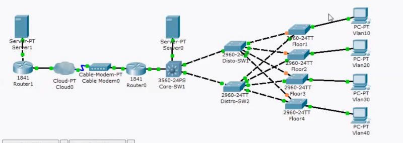
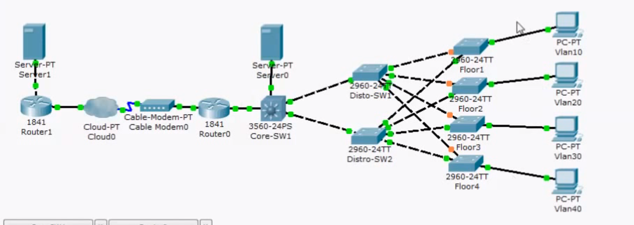
ASKER
Have done some research based on the diagram above:
All the Access switches will have redundant trunks to Distribution switches SW1 and SW2
the Distribution switches will have each a trunk to core switch (L3).
Core switch will be the VTP server and all other Switches will be VTP Clients.
Core Switch will be set up to priority 0 so that it will become root switch, Distro switches will have priority higher than Core switch, Access switches will have priority higher than Distro switches.
Create an SVI for VLAN management and assign it IP address, instead of the default VLAN1 management interface. We need to do this on each switch with different IP address for each VLAN Management interface.
In core switch create SVIs for each VLAN in the Network and assign them IP addresses, these SVI will server as the Default Gateway for the PCs.
To make access to the all switches secure we can configure on each switch user name and password and enable ssh:
Line vty 0 4
login local
transport input ssh
you can encrypt the login session to the switch by using crypto key:
Crypto key Generate rya
On each switch configure the Default Gateway Ip address that points back to Core Switch Management Interface IP address.
We need to type IP Routing command on Core Switch will this will enable us to route between all VLANs in the network since respective interface VLANs have been created on the core switch.
for the core switch interface connected to the Router, we can run NO switch port command on that interface and assign it an IP address.
On the core switch , for each interface VLAN (SVI) we create for a specific VLAN, we need to specify the IP helper Address that points to DHCP server IP address.This way each PC communicating with its DG can find the DHCP server.
On the core switch route everything to the Router interface :
IP Route 0.0.0.0.0.0.0.0 192.168.0.1
This way PCs can access resources that L3 switch does not know about.
On the router Interface facing ISP we can configure:
IP address DHCP (it gets IP from ISP DHCP server)
IP NAT Outside
On the Router Global config we'll create Access lists that permits traffic destined to the subnets inside the network
Acces list 1 permit 192.168.1.0 0.0.0.255
Acces list 1 permit 192.168.2.0 0.0.0.255
and always on the Router Global Config we'll route the traffic destined to the inside subnets to go to the interface of L3 switch
IP Route 192.168.0.1 255.255.255.0 192.168.0.1
IP Route 192.168.0.2 255.255.255.0 192.168.0.2
on the interface facing L3 Switch, we configure:
Ip address 192.168.0.1 255.255.255.252
IP NAT inside
ASKER
I wonder if that 's correct
ASKER
Thank you
ASKER
I wanted to know the general concept on how to connect Computers to the Network.
let's say we have a company that has 400 workstations and Servers together and need to be connected to the network.. I basically need to know the road map….
for instance connect computers to separate VLANs on switches , make computers capable of communicating between each other and the outside world…