Simple 3D CAD
I need to make a simple 3D object as follows:
- A cylinder flat as a disk. The diameter is 150mm and thickness 40mm.
- I need to drill (through) a hole 10mm in the center of the disk.
- The last action: by sides, on 8 points equal distance between them, around the perimeter of the circle, at the middle of the thickness, I need to drill holes with diameter 20mm and depth 25mm.
That is all, quite simple. I do not need sophisticated programs.
What program do you recommend me as for a beginner, something that I learn in 30min max. ?
I tried Sketch up which is intuitive, and easy to play, but making the holes by side seems a terrible job to do with intersections. Something else more simple?
Do not tell me about Autocad, SolidWorks, Catia, ProEngineer or other sophisticated programs.
If it is something that I cannot understand in 30min, forget it.
I have seen a big list of free CAD packages. I even tried some but I could not learn easy.
I need something easy and fast. It is a simple task.
I looked at some as: OpenScad, Blender, Wings, 3D Crafter, NaroCAD, FreecAD, 123Design, Houdini…, but are too many and I do not know which one can do the job easy and fast.
Any suggestion?
ASKER CERTIFIED SOLUTION
membership
This solution is only available to members.
To access this solution, you must be a member of Experts Exchange.
SOLUTION
membership
This solution is only available to members.
To access this solution, you must be a member of Experts Exchange.
ASKER
Thank you very much for the steps.
They are very helpful in case I decide for viaCAD.
I have only 2 questions:
1) When you made the holes by side with that 20x20x26 cylinder, how did you make sure and positioned the cylinder that the holes are exactly 25mm depth?
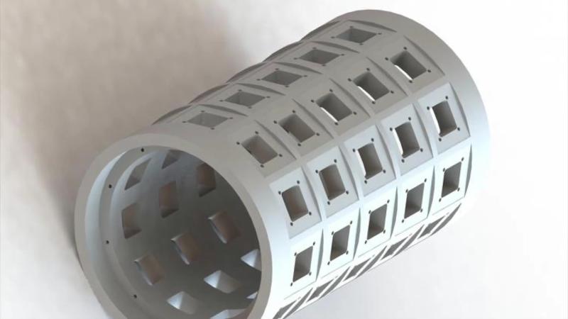
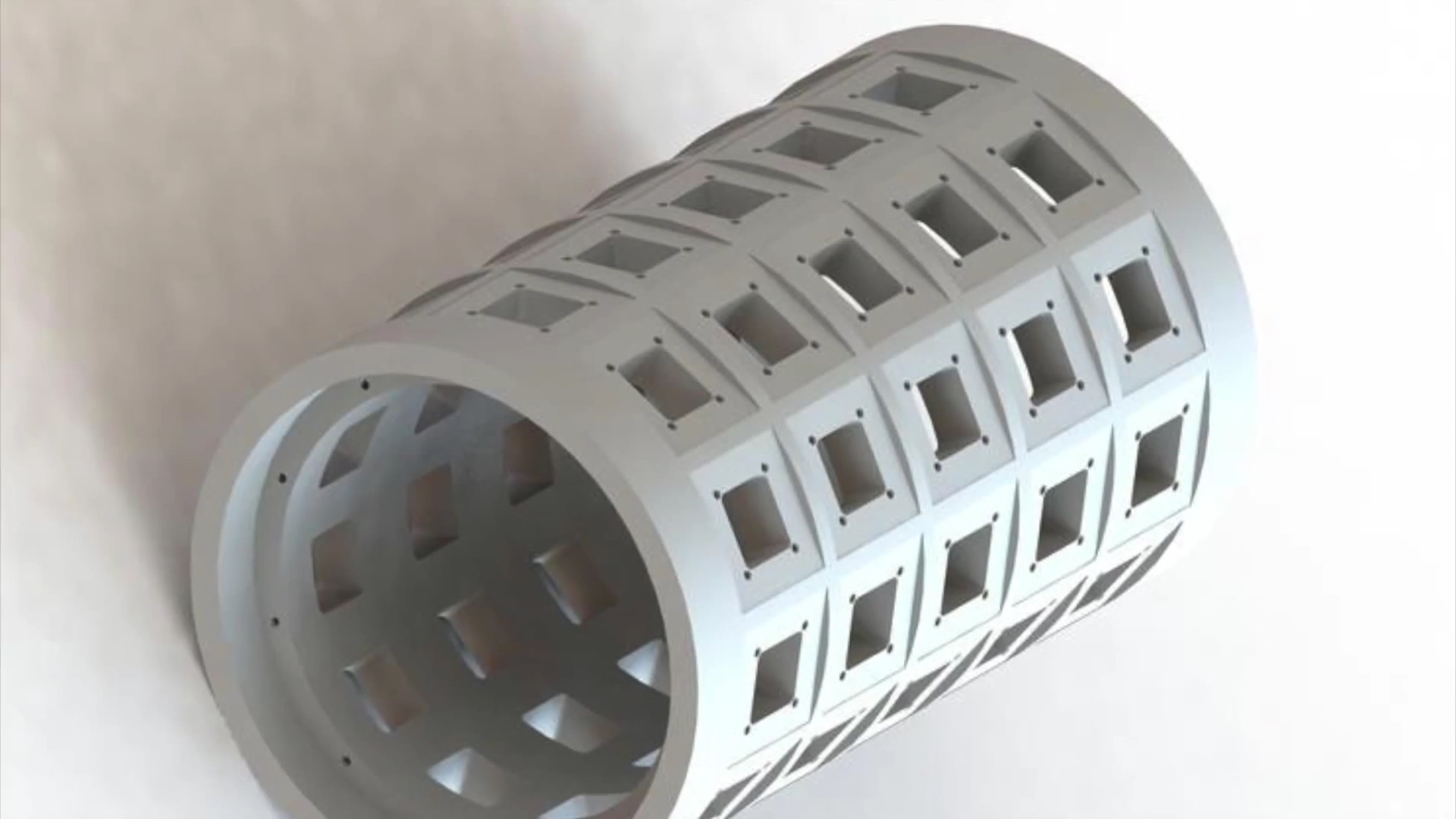
2) How difficult do you expect to be done (how long time) a solid model as in the picture below?
They are very helpful in case I decide for viaCAD.
I have only 2 questions:
1) When you made the holes by side with that 20x20x26 cylinder, how did you make sure and positioned the cylinder that the holes are exactly 25mm depth?
2) How difficult do you expect to be done (how long time) a solid model as in the picture below?
SOLUTION
membership
This solution is only available to members.
To access this solution, you must be a member of Experts Exchange.
SOLUTION
membership
This solution is only available to members.
To access this solution, you must be a member of Experts Exchange.
ASKER
Would you mind to share the steps for the above model before I close the question?
Or do I ask already too much?
Or do I ask already too much?
I don't mind sharing the steps I took to create the new object. It may be a few hours before I can get to it though.
ASKER
It is all right if I have them tomorrow or during the next days. It is not such a hurry. In mean time I test different CAD programs to see which one fits better to my style.
Anyway, for me would 1 or 2 times job, maybe 5-10 times worse case. I will not do that all the time.
Anyway, for me would 1 or 2 times job, maybe 5-10 times worse case. I will not do that all the time.
SOLUTION
membership
This solution is only available to members.
To access this solution, you must be a member of Experts Exchange.
SOLUTION
membership
This solution is only available to members.
To access this solution, you must be a member of Experts Exchange.
ASKER
The videos arrived well on my side and I could watch them.
I will try to apply the steps with other CAD programs to which I have access.
Maybe I will post later the results.
For now I will close the question. You already did far beyond the scope of the question.
Many thanks for all the effort!
I will try to apply the steps with other CAD programs to which I have access.
Maybe I will post later the results.
For now I will close the question. You already did far beyond the scope of the question.
Many thanks for all the effort!
ASKER
Now I have one song in my mind that bother me terrible: "I Wanna Be Like You" : )
https://www.youtube.com/watch?v=EKnQoWWySm8
https://www.youtube.com/watch?v=EKnQoWWySm8
It felt good to finally practice some 3D drawing. It's something I've been interested in for some time but never have the time nor necessity to practice. Forty years ago I graduated from a trade school for drafting and went to work for an architect. Then I became a builder. The thing about drafting (with pencil on paper) and building for that matter is that they are primarily additive processes. To build a house for example, you buy tons of materials and ADD them together to form enclosed rooms with holes for doors and windows. The strange part of 3D CAD for me is that it's as much a subtractive process as it is an additive one. It's like building a house by starting with a solid block and subtracting volumes from it to form rooms, doors and windows. It feels very unnatural to a builder to work that way.
Thanks for the points.
Thanks for the points.
ASKER
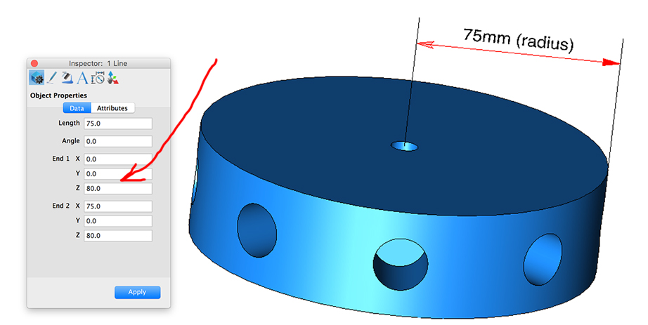
Apprentice work with viaCAD, but I still not get how to put dimensions on the solid as diameter of the holes and the height of the disk:


You can add dimensions to the 3D rendering if you like by using lines with or without arrow head ends and text. Just like any 3D object the lines and text must be positioned on all 3 axises using the properties window for the object. However, they will only read properly from a small range of angles without distortion or backwards writing. From an engineering standpoint, this is not the standard approach. The object would be drawn in 2D from all necessary angles (top, side, cross section, etc) and dimensioned there. Then, a 3D rendering may be provided for clarification purposes only. A fabricator would never build from the 3D rendering.
3D CAD programs like ViaCAD usually have both 2D and 3D interfaces for this purpose. In ViaCAD you switch between the two at the top of the toolbox.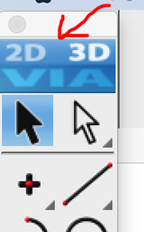
 From an engineering standpoint, this is not the standard approach. The object would be drawn in 2D from all necessary angles (top, side, cross section, etc) and dimensioned there. Then, a 3D rendering may be provided for clarification purposes only. A fabricator would never build from the 3D rendering.
3D CAD programs like ViaCAD usually have both 2D and 3D interfaces for this purpose. In ViaCAD you switch between the two at the top of the toolbox.
ASKER
Thank you for the explanations.
Just an aside note.
Seems that ViaCAD shares (or shared) the same interface with TurboCAD:
https://www.youtube.com/watch?v=qzElhvaVpSE
Here is a German discussion about it, you have to read with Google chrome for auto translate:
http://www.macuser.de/threads/deja-vue-erlebnis-punch-viacad-2d-3d-v9-turbocadmacdeluxe7.727785/
Some other discussions:
http://cad.softwareinsider.com/compare/31-59/TurboCAD-LTE-vs-ViaCAD-2D-3D
http://tcmacforum.imsisupport.com/index.php?topic=1854.0
http://forums.turbocad.com/index.php?topic=12256.0
Very interesting. The two programs look almost identical. There is much more to learn about 3D CAD.
ASKER
It would be nice if you can share the steps.
In mean time I found also the right menus and tools for Sketchup.
The holes in round shapes must be done with cylinder intersection set as solid/component.
The for through hole is needed intersect faces with model or with selected.
To rotate proper the cylinder made from a circle and applied push-pull you have to make it component.
Then you put it through the disk. The difficulty is to align it proper, each time for one hole. You need guides, lines.
Then the last catch is to have both: the cylinder as drill bit and the disk as main plate/model as component before intersection and final step is to apply Tools- Solid Tools- Split, otherwise we get an empty disk inside, because Sketchup is a surface 3D and not a true solid 3D.
But it took me few hours to learn all these from scratch following some tutorials.
Sketchup is not so good at curved surface. It is good at push-pull.