Bearing type and size
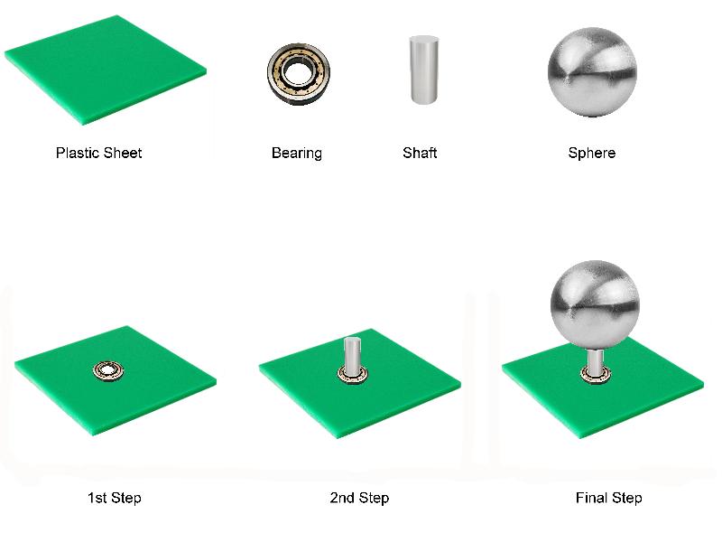
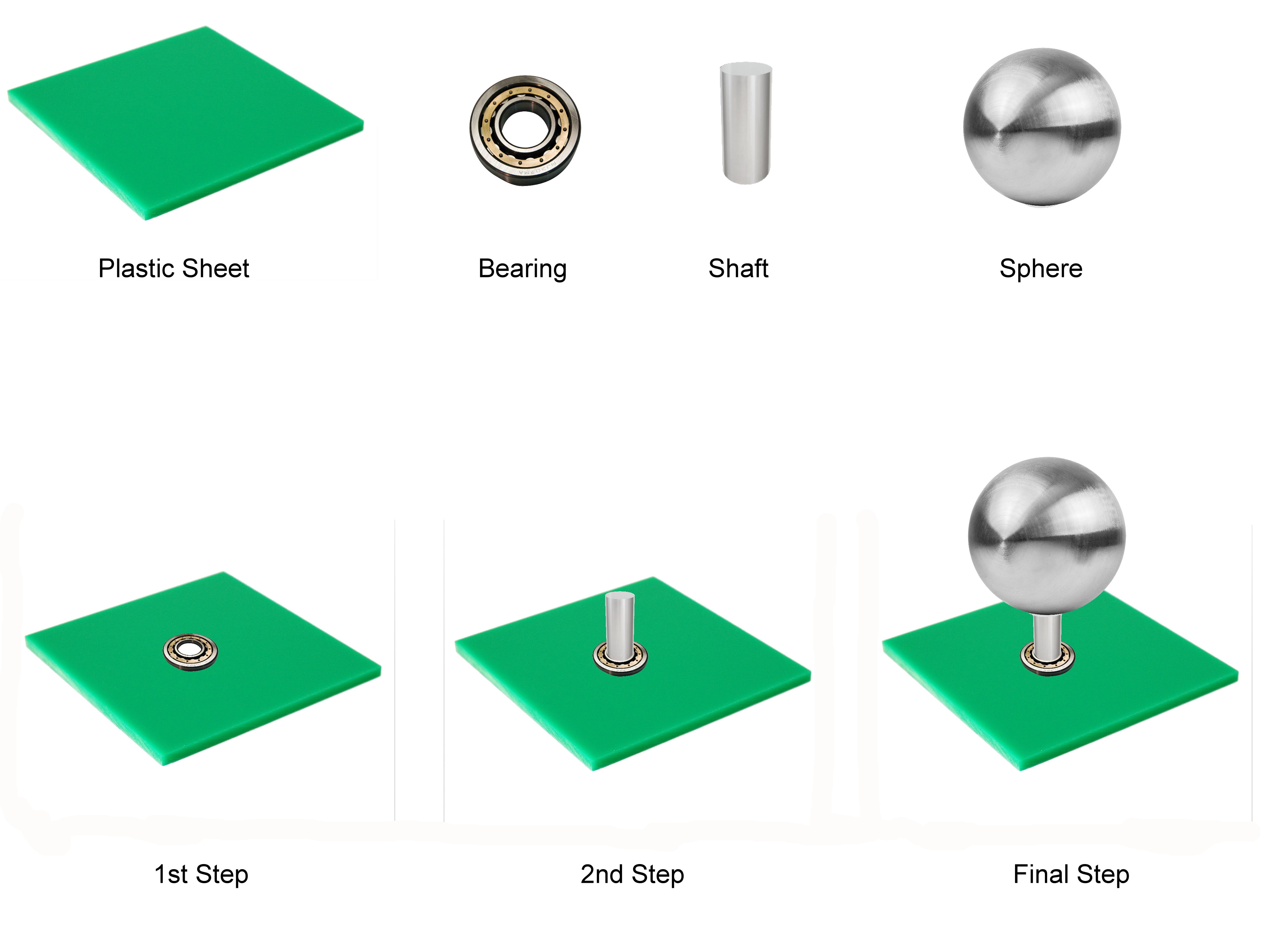
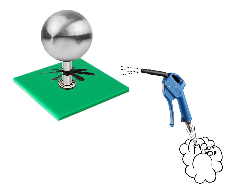
Assuming I have a plate as below with a hole in which I install a bearing.
Then I insert a shaft and in top of the shaft a weight. Let’s say is a round weight, can be a sphere or a disk.
Questions:
- What type of the bearing should I use?
- From what material should be the bearing made?
- What size should be the bearing?
The purpose is to have the lowest possible friction using bearing that I can buy from market.
Plate: 30 x 30 cm
Weight: max. 20cm diameter and 1-2Kg
dbrunton
Does the shaft transmit it's turning motion through the plastic plate or is the primary purpose of the shaft to support the weight of the ball on top of the plastic plate and permit turning motion?
What will stop the shaft from sliding right through the bearing until it is stopped by the weight on top of it?
Is the plate always going to be horizontal with the shaft going through it vertically, or will the shaft ever be horizontal?
Is the plate always going to be horizontal with the shaft going through it vertically, or will the shaft ever be horizontal?
ASKER
The plastic is just a steady support that never turns.
The purpose of the plastic sheet is only to keep the bearing in place. Imagine that the bearing is somehow embedded, incastrated in the plastic sheet. The bearing is fixed there in the plastic with its outer shell. There is s hole in the plastic which allows the center of the bearing to move freely.
The shaft is fixed in the inner side of the bearing and at the end on the top is the weight.
The weight, the shaft and the inner side of the bearing move freely all together. The plastic sheet does not move, it just keeps the bearing in place. It is a simple construction, nothing fancy or sophisticated.
The shaft does not slide through the bearing. We can achieve that with various methods, for instance imagine the diameter of the shaft is increasing with few mm and then the shaft is stacked in the inner side of the bearing due to the weight/gravity.
The plate is always horizontal and the shat is always vertical.
It is just a simple construction where a weight as a sphere or can be a thick disk is attached to a shaft and inserted in a bearing with only one purpose: to move freely, with lowest possible friction. It is nothing else.
At this stage, the above is just a theoretically experiment. I want to understand before I move to practical tests. The pictures above are only photo editing steps, it is not any real setup. I made that picture so you can understand better the setup looking at picture rather then using only words.
You may consider the plastic plate bigger if you consider is not stable, let's say 50X50cm and 5cm thick. It is not important. Just consider it a stable horizontal plate. It can be a table sheet which holds the bearing steady.
My focus is on bearing.
I hope I answered your questions. If not please ask more details.
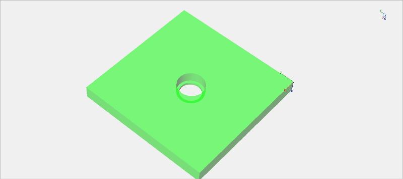
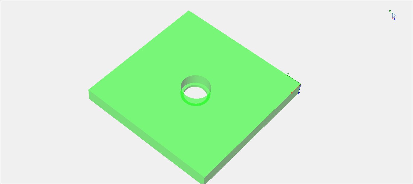
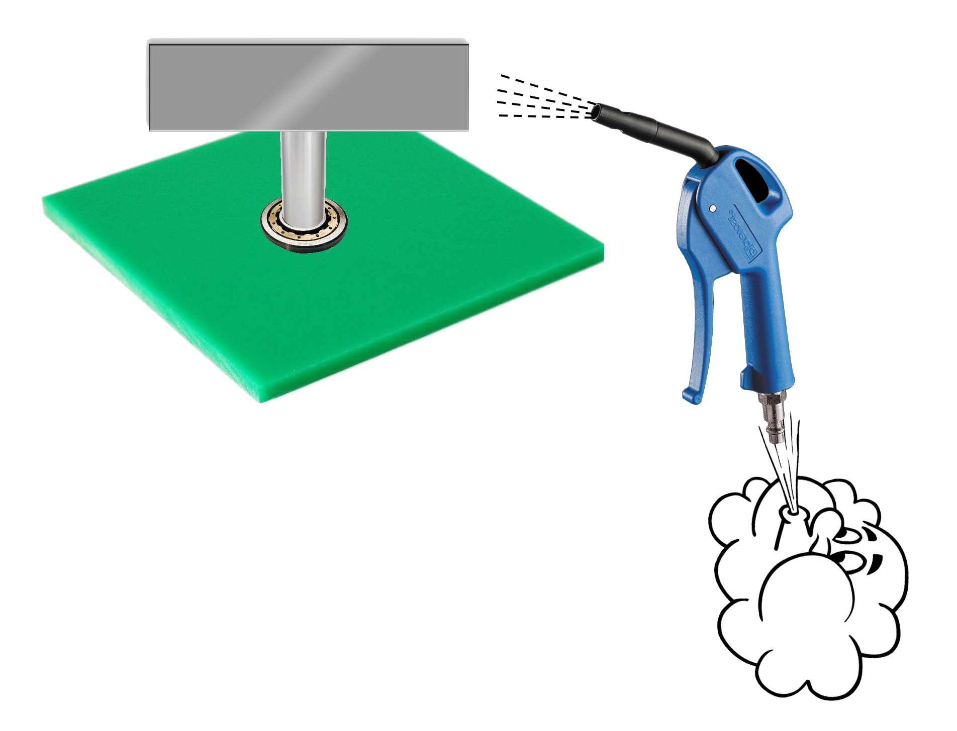
Let's say the plastic sheet has a hole with a small shoulder to avoid the bearing sliding through the hole as in the picture below:
The purpose of the plastic sheet is only to keep the bearing in place. Imagine that the bearing is somehow embedded, incastrated in the plastic sheet. The bearing is fixed there in the plastic with its outer shell. There is s hole in the plastic which allows the center of the bearing to move freely.
The shaft is fixed in the inner side of the bearing and at the end on the top is the weight.
The weight, the shaft and the inner side of the bearing move freely all together. The plastic sheet does not move, it just keeps the bearing in place. It is a simple construction, nothing fancy or sophisticated.
The shaft does not slide through the bearing. We can achieve that with various methods, for instance imagine the diameter of the shaft is increasing with few mm and then the shaft is stacked in the inner side of the bearing due to the weight/gravity.
The plate is always horizontal and the shat is always vertical.
It is just a simple construction where a weight as a sphere or can be a thick disk is attached to a shaft and inserted in a bearing with only one purpose: to move freely, with lowest possible friction. It is nothing else.
At this stage, the above is just a theoretically experiment. I want to understand before I move to practical tests. The pictures above are only photo editing steps, it is not any real setup. I made that picture so you can understand better the setup looking at picture rather then using only words.
You may consider the plastic plate bigger if you consider is not stable, let's say 50X50cm and 5cm thick. It is not important. Just consider it a stable horizontal plate. It can be a table sheet which holds the bearing steady.
My focus is on bearing.
I hope I answered your questions. If not please ask more details.
Let's say the plastic sheet has a hole with a small shoulder to avoid the bearing sliding through the hole as in the picture below:
SOLUTION
membership
This solution is only available to members.
To access this solution, you must be a member of Experts Exchange.
SOLUTION
membership
This solution is only available to members.
To access this solution, you must be a member of Experts Exchange.
SOLUTION
membership
This solution is only available to members.
To access this solution, you must be a member of Experts Exchange.
ASKER
I need a better answer. Here it is why.
Before I asked the question here, I already searched the internet couple of days and I have read different info about the bearings. Then my head became bigger and the multitude and variation of info acquired started to be mixed up in my head resulting a salad. Nevertheless, I can still filter and split the question asked in clear more specific questions.
Here are some sources that I went through:
http://www.kaydonbearings.com/typesACX.htm
https://www.engineeringclicks.com/ball-bearings-guide-to-selection-applications-calculations/
http://webtools3.skf.com/BearingCalc/selectProduct.action
Then next:
http://www.popularmechanics.com/technology/gear/a15603/super-efficient-greaseless-bearings/
and one of the best:
http://web.mit.edu/2.75/fundamentals/FUNdaMENTALs%20Book%20pdf/FUNdaMENTALs%20Topic%2010.PDF
And general info as:
http://www.hardwaremarketplace.com/information-guide/types-of-bearings.html
http://www.thomasnet.com/articles/machinery-tools-supplies/bearing-types
http://science.howstuffworks.com/transport/engines-equipment/bearing3.htm
http://info.craftechind.com/blog/bid/371106/6-Most-Popular-Types-of-Mechanical-Bearings
http://www.engineersedge.com/bearing_types.htm
and some more…
Strange that no one asked me so far, and I forgot to mention it: what is the speed of the shaft?
Probably you assumed that I spin it by hand.
It is around 600 RPM, easy to be handled by most of the bearings. The worse case would be 10 times higher around 6000 RPM, but for the moment we consider it 600 RPM.
I do not intend to use magnetic bearing, unless is somewhere with permanent magnets only, accessible price, but here is a big discussion and we should ignore it for the moment, unless you point to a direct manufacturer/product that I can check it. I do not intend to use hydrodynamic, aerostatic or hydrostatic bearings.
Basically I just want a simple mechanical bearing, probably with balls, unless a nice magnetic bearing with permanent magnets is indicated.
Then comes the force.
My initial drawing and explanations says about a weight (sphere or disk) of 1-2kg. That makes you think that only the gravity force perpendicular on the bearing is present and therefore a thrust ball bearing would be enough.
If the shaft rotates with 600RPM then must be something to rotate it.
Let’s consider a air blow pressure from the side, thinking we have a propeller attached to the shaft or if instead of the sphere/disk weight there is a rectangular metal weight (as propeller) and I blow the air onto it.
Then we have also radial force and the thrust bearing is not good anymore.
Let’s break the initial questions in more specific questions:
1) When I asked what size, I had in mind next:
a. Should it be 1mm bearing or 10cm bearing? Why one or another?
b. Is it any optimum size in-between? How do you know what size to choose?
c. There are sizes having the same inner diameter, but different outer diameter. Which one to choose? Keep in mind that I am flexible with what inner and outer diameter I can choose. I am not force by the setup to a specific diameter.
The only explanation that comes into my mind now to choose a specific size is related with next things:
- A smaller size my imply a lower friction – this is what I need.
- A too small size will not assure the stability of the load, the shaft with the weight when rotates with 600 RPM.
- And opposite: higher size gives stability but too much friction.
From here the question: how to choose proper the size knowing the size, the weight of the load and the construction setup?
2) When I asked about type, I had in mind next:
a. Axial, radial, thrust, ball, rolls…whatever mechanical constriction has the bearing.
Which one is better for me, knowing the size, the weight of the load and the construction setup, shaft position, speed of the shaft, forces on the shaft…, considering lowest possible friction?
I was thinking at rolls bearings which can support also radial force.
But then comes next (http://www.kaydonbearings.com/typesACX.htm): angular contact, radial contact, 4 points contact or whatever else may be…?
What about the cage for balls? With or without or what type?
Logical sounds without cage less friction, but would that give enough stability to ky setup? I do not have another bearing on the top.
b. Material: should be stainless steel, or special plastics or ceramic?
I have read a lot about ceramic bearings having 10 times less friction than normal steel bearings. I do not know about plastics. Can you tell me something?
c. I do not want to lubricate the bearing, unless is really lower friction. I know that are some self-lubricating materials, but I do not think are used for such bearings. Any idea?
Maybe this construction without cage (http://www.popularmechanics.com/technology/gear/a15603/super-efficient-greaseless-bearings/
) and ceramic type will be lowest friction, but I need to buy something available on the market. And I am not so sure about such bearing without cage when are radial forces involved.
Speaking about ceramic bearings, I discussed with the next company (http://www.lily-bearing.com/ceramic-bearings/ ) and they recommended me ZrO2 as lowest friction.
They have a lot of types (http://www.lily-bearing.com/ceramic-bearings/ceramic-deep-groove-bearing/metric-sizes/ ).
The y asked me 100$ for one piece having 10mm inner diameter, 20-20mm outer diameter and width 5-10mm.
I found on German market 30-40€ for such bearing. On Ali-Express it is a lot cheaper, only that takes weeks.
Please give me more details about type and size as I described above.

you're like the wind on the Ventoux...
ASKER CERTIFIED SOLUTION
membership
This solution is only available to members.
To access this solution, you must be a member of Experts Exchange.
ASKER
If it is of any help, I can consider the weight lower, down to 0.5Kg.
We can consider also the radial forces that turns the shaft equal distributed around 360°, so not only one force from one side.
We can imagine an AC squirrel motor where my shaft is the rotor, but only vertical position and max. 600RPM. Then you can imagine the electromagnetically forces distributed around the rotor.
Normally I need a 2nd bearing on the top, but only because I need the lowest friction I would like to use only one bearing at the bottom. We can imagine a flat rotor as a disk, where the diameter is longer than thickness.
The purpose of the lowest friction is to keep the rotor in motion with the lowest possible current in the coils of the stator. We may assume that I put the rotor in motion by hand only to break the initial torque.
ASKER
@ Michael-Best
How do you choose the size?
How do you choose the size?
無理デs
ASKER
Does that mean "Unreasonable error" or "Impossible"?
SOLUTION
membership
This solution is only available to members.
To access this solution, you must be a member of Experts Exchange.
SOLUTION
membership
This solution is only available to members.
To access this solution, you must be a member of Experts Exchange.
ASKER
@Michael-Best
Testing would not be a problem, but when a good ceramic bearing is 50€ or 100$ for a small size, then it would be good to know at least around what size should I pick up one related with the load and construction. I need to understand why one size or another.
I do not want to spend hundreds of $ for some bearings only to try them and choose one. I would like to know in advance.
When you say Bearing Load = Weight x RPM x Cooling Factor, is the Cooling Factor specific for each bearing and can be found in the manufacturer catalogue?
@dbrunton
Let's consider is electrical driven by electromagnetic forces.
These are distributed around. Does that mean will help to center the rotor?
It is true that at high speed the rotor fixed only on one bearing it may start wobbling, even shacking and destroying the bearing, but let's consider few factors here: if the rotor-disk is made out of homogeneous material and is high precision cut and drilled, let's say 0.1mm precision (100um) then at certain load and certain speed a certain tolerance is allowed as deviation from center. That deviation from center of gravity will make a center moment, unbalance. but it may be within acceptable limits if some relations between these values are respected.
For instance, here is a document, which on page 3-5 show that relation:
http://www.irdbalancing.com/downloads/techpaper1balqualityreqmts.pdf
What do you think?
Now, let's suppose the limits of displacement are not respected due to tolerances of rotor manufacture, is then the usage of the second bearing on the top a help to have lower friction for the rotor compared with the situation when only one bearing is used and the center of gravity vs weight vs RPM and is outside of the recommended limits and starts wobbling?
In other words I see these 2 options and I do not know which one is better for lower friction:
1) Using only one bearing and making high precision rotor
2) Using 2 bearings and lower tolerances for rotor
For me important is only to have the lowest possible friction, the rotor to move as easy as possible, driven with lower possible electromagnetic field, even if I start the rotor by hand initially, because the start moment involves always high inrush currents and more energy than when is in motion.
SOLUTION
membership
This solution is only available to members.
To access this solution, you must be a member of Experts Exchange.
ASKER
OK.
I see that is a complex situation to decide and I might need some practical tests.
Now, at least minimum to start: what bearing size should I use and why? Should it be 5mm diameter or 30mm diameter. Ho do I accommodate the diameter with the load and the construction? Based on what criteria?
I see that is a complex situation to decide and I might need some practical tests.
Now, at least minimum to start: what bearing size should I use and why? Should it be 5mm diameter or 30mm diameter. Ho do I accommodate the diameter with the load and the construction? Based on what criteria?
SOLUTION
membership
This solution is only available to members.
To access this solution, you must be a member of Experts Exchange.
ASKER
Here is one more piece of info that I came across few weeks ago and I lost it in mean time.
Electrodynamic bearings, but from where to buy 1-2 pcs only?
https://www.youtube.com/watch?v=2R4QQmCY4JU
http://www.magnetal.se/
http://www.magnetal.com/
http://www.magnetal.se/Technology.html
http://www.magnetal.se/ProductsPMB.html
https://www.calnetix.com/sites/default/files/Flywheel-Homopolar.pdf
SOLUTION
membership
This solution is only available to members.
To access this solution, you must be a member of Experts Exchange.
ASKER
I did. I opened them. The DC brushless type. Yours is AC, but maybe the bearings are similar.
I know the DC type. Maybe a different brand/company. I can post photos Monday.
It has a permanent round magnet round inside the propeller, which is the rotor and 4 coils/electromagnets with a small PCB that pulses the energy on the coils in a certain sequence. Sometimes they have a 3rd wire for "tacho"/encoder signal feedback to know the speed.
Mechanically they have a small bearing inserted on a tube metal or pals tic, the bearings is somewhere in the middle of the shaft, but the shaft attached to the propeller has one end fixed on a kind bushing fixed with a locking washer
Here are some pictures of the common types:
http://www.pcbheaven.com/wikipages/How_Brushless_Motors_Work/
http://www.hardwaresecrets.com/anatomy-of-computer-fans/2/
The documents that I have read so far says that ceramic ZrO2 have 10 times less friction than a normal metal bearing. That means if I use 2 small ceramic bearings, one on top and one on bottom is still lower friction than a single metal type.
Because it just happen to have some small bearings from DC brushless fan, I will try with those in the beginning.
SOLUTION
membership
This solution is only available to members.
To access this solution, you must be a member of Experts Exchange.
What is it you are trying to do?
Are you trying to build your own disk drive?
Are you trying to build your own disk drive?
ASKER
It is an experiment. For the moment mental stage.
For the purpose of discussion let' imagine a shaded-pole motor:
https://en.wikipedia.org/wiki/Shaded-pole_motor
which is only in vertical position and would be good to be only with one bearing at the bottom for lower friction.
I am trying to drive it with lower possible currents.
I am still thinking at ceramic bearings, being considered 10 times lower friction than the others, despite the higher prices. I guess 1 or 2 I can afford. I need only to know what size should I order.
ASKER
I looked one more time at the brushless DC fan that I have.
It has a metal tube on center and 2 small bearings, one close to each end.
I removed all the wires, PCB, coils, plastics and 4 metal lamination that makes the electromagnets.
I remain only the tube in center, the plastic housing and the 2 bearings.
I reduced the weight and the size of the disk (diameter 12cm only) and I will give it a try like that.
Maybe later I will try a ceramic bearing too, similar size or the smallest that I can find on the market.
So I have now 2 small bearings on one tube. If it is not centered enough and is wobbling then I will use a second similar dismantled fan on the top, but that requires an additional construction with a plane on top side and 3 or 4 pillars. And then comes of problem of having upper plane parallel and centered with bottom plane, if not then it will be additional tension and friction on bearings if they are not aligned, which is not always so easy only with hobby tools. That's why I prefer for the moment only the bottom bearings.
ASKER
Thank you for suggestions.
Any tips how to align the top with the bottom plane using simple hobby tools are welcome.
Any tips how to align the top with the bottom plane using simple hobby tools are welcome.
If you drill the top and bottom plates together, pinning them with zero tolerance dowels as you go, you should have pretty good results.
Do you have access to a small drill press, or just a hand drill? You can get reasonable results with a hand drill if you clamp the pieces together and use a vertical guide block.
Do you have access to a small drill press, or just a hand drill? You can get reasonable results with a hand drill if you clamp the pieces together and use a vertical guide block.
ASKER
Overlaying top and bottom planes, fixing them together and then drilling them is something that I already imagined and tried with other occasions.
I have only a hand drill.
And here starts the problem.
If I drill by hand, then the holes are not necessarily perpendicular on the planes. The drill goes astray, oblique, not making a 90° hole.
I do not have that vertical guide block. I must make one somehow.
Then comes next.
Assuming I have the holes pretty decent drilled, then I must lift up the upper plane/piece and use some spacers, equal dimension blocks, threaded rods.
When the distance increases between planes, even if the holes are drilled perfect, overlaying, there is still a problem of alignment in space: the planes may not be parallel anymore or the holes shift left/right for example, x/y/z alignment is not so easy.
I had in mind the usage of a thread rods or ready-made commercial spacers equal dimension, so I can rely on their dimensions and then just to try it out and see how easy the disk will spin when the the setup is finished.
I think I have to have in mind a way of correction/adjustment for the spacers, in case one is a bit shorter than another and the planes are not parallel anymore.