Batch of Internet IPs on Cisco 1921 router
We have two sites with a Cisco 1921 router at each. Each has a VDSL HWIC and a batch of 8 IP addresses assigned by the ISP, with the inside interface (GigabitEthernet 0/0) connected to a pfSense firewall. We have it working with a single IP assigned to the pfSense using the config below, but would like to make use of more IP addresses. How can we configure the Cisco 1921 to allow this? It's not possible to configure the inside and outside interfaces on the same subnet, so we split the 8 address subnet into two.
For this config, the assigned IP range is xxx.xxx.xxx.8/29, and the IP being automatically assigned by the ISP is xxx.xxx.xxx.9/32. The pfSense firewall is on xxx.xxx.xxx.14/30.
For this config, the assigned IP range is xxx.xxx.xxx.8/29, and the IP being automatically assigned by the ISP is xxx.xxx.xxx.9/32. The pfSense firewall is on xxx.xxx.xxx.14/30.
version 15.1
service timestamps debug datetime msec
service timestamps log datetime msec
no service password-encryption
!
hostname Router
!
boot-start-marker
boot-end-marker
!
!
enable secret 4 ######
!
no aaa new-model
!
no ipv6 cef
ip source-route
ip cef
!
!
!
!
!
multilink bundle-name authenticated
!
crypto pki token default removal timeout 0
!
!
license udi pid CISCO1921/K9 sn #####
!
!
username ##### secret 4 #####
!
!
controller VDSL 0/0/0
 operating mode vdsl2
!
!
!
!
!
interface Embedded-Service-Engine0/0
 no ip address
 shutdown
!
interface GigabitEthernet0/0
 ip address xxx.xxx.xxx.13 255.255.255.252
 duplex auto
 speed auto
!
interface GigabitEthernet0/1
 no ip address
 shutdown
 duplex auto
 speed auto
!
interface ATM0/0/0
 no ip address
 shutdown
 no atm ilmi-keepalive
!
interface Ethernet0/0/0
 no ip address
 no ip route-cache
!
interface Ethernet0/0/0.101
 encapsulation dot1Q 101
 ip address dhcp
 ip virtual-reassembly in
 no ip route-cache
 ip tcp adjust-mss 1452
 pppoe enable group global
 pppoe-client dial-pool-number 1
!
interface Dialer1
 ip address negotiated
 no ip unreachables
 ip mtu 1492
 ip virtual-reassembly in
 encapsulation ppp
 dialer pool 1
 dialer-group 1
 ppp authentication chap pap callin
 ppp chap hostname #####
 ppp chap password 0 #####
 ppp pap sent-username ##### password 0 #####
 ppp ipcp dns request
 no cdp enable
!
ip forward-protocol nd
!
no ip http server
no ip http secure-server
!
ip route 0.0.0.0 0.0.0.0 Dialer1
!
!
!
!
control-plane
!
!
!
line con 0
 logging synchronous
line aux 0
line 2
 no activation-character
 no exec
 transport preferred none
 transport output pad telnet rlogin lapb-ta mop udptn v120 ssh
 stopbits 1
line vty 0 4
 logging synchronous
 login
 transport input all
!
scheduler allocate 20000 1000
endASKER
What exactly do you mean by "a routed subnet between the router and the service provider"? I've seen it before where a single (unrelated to the /29 batch) IP is assigned to the outside interface, leaving the whole /29 usable (with one allocated to the inside interface of course) - is that what you mean?
How would the /31 subnets work?
We don't require any NAT or PAT, as the pfSense firewall inside will do all that. We simply want to route the IPs through from the outside to the inside.
Thanks!
How would the /31 subnets work?
We don't require any NAT or PAT, as the pfSense firewall inside will do all that. We simply want to route the IPs through from the outside to the inside.
Thanks!
That is correct, i have worked in a service provider where we have used a private IPs between the SP and the CE of the client so they can benefit from all the public IPs assigned to them.
For /31 subnets it simply works for point to points (usually serially interfaces) but also can used on ethernet where you only have two endpoints on the segment. Some devices would refuse the config of 255.255.255.254 subnet mask
There is an RFC that allows this for point-to-point connections:
http://tools.ietf.org/rfc/rfc3021.txt
In your situation, i would simply statically route each of the the remaining IPs to the inside next hop and use them internally by the Natting device
ASKER
Great, thanks. What would the commands be to statically route the remaining IPs to the inside next hop?
What is the ip address of your next hop? (Service provider?
Show ip route on the router will clarify this
Show ip route on the router will clarify this
ASKER
Here's the output.
The first two octets of the top two redacted addresses are the same, as are the first three octets of the bottom four addresses.
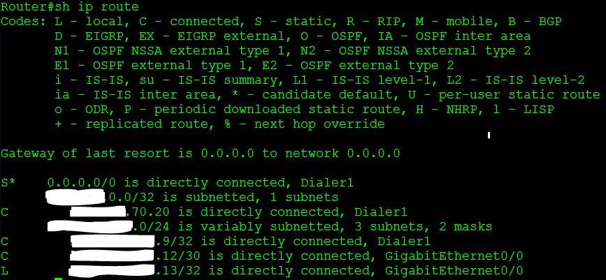
The first two octets of the top two redacted addresses are the same, as are the first three octets of the bottom four addresses.
ASKER CERTIFIED SOLUTION
membership
This solution is only available to members.
To access this solution, you must be a member of Experts Exchange.
ASKER
Great. What are the commands to do this please? Also do I have to reconfigure the subnet GigabitEthernet0/0 and the IP address on Dialer1? Thanks.
I would leave the pfsense connectivity as is, in order not to break it as we are not sure if it supports /31 subnet masks and utilise the two remaining public ip addreses
(config)#ip route x.x.x.10 255.255.255.255 x.x.x.14
(config)#ip route x.x.x.11 255.255.255.255 x.x.x.14
Then nat the 10 and 11 public ip addreses on the pfsense for them to be reached from the internet
(config)#ip route x.x.x.10 255.255.255.255 x.x.x.14
(config)#ip route x.x.x.11 255.255.255.255 x.x.x.14
Then nat the 10 and 11 public ip addreses on the pfsense for them to be reached from the internet
ASKER
Thanks, we'll give it a try.
ASKER
We weren't able to get this to work in the end, and gave up. We're grateful for the helpful input, though!
If you can have a routed subnet between the router and the service provider and the /29 is internally assigned ?
Another option would go to /31's which is allowed in cisco (but shall confirm other side)
The easiest way in your setup is to nat (one to one any of your private ip addresses to external public addressing)
Do yo require pat (overloading) or static one to one natting?