Rocco Galati
asked on
Equations for Dynamics of Tracked Vehicles
Hi to all,
I would like to be able to write equations to model my tracked vehicle which has a mass m=200Kg.
My skid-steering vehicle uses one track per side with a rubber belt made in 100% natural rubber, please refer to the next photo to get a more detailed idea.
Since I mounted an IMU in its geometric center, I can read both the angular velocites and the accelerations along the three axis plus the heading, the pitch and yaw angles in degrees.
I would like to be able to write a model for the vehicle in order to simulate and study its outputs depending on specific inputs.
Each track has a length L=1000 mm, a width W=330 mm and a lug height, H = 32 mm.
The vehicle is Lv= 1000 mm long and Wv=900 mm width.
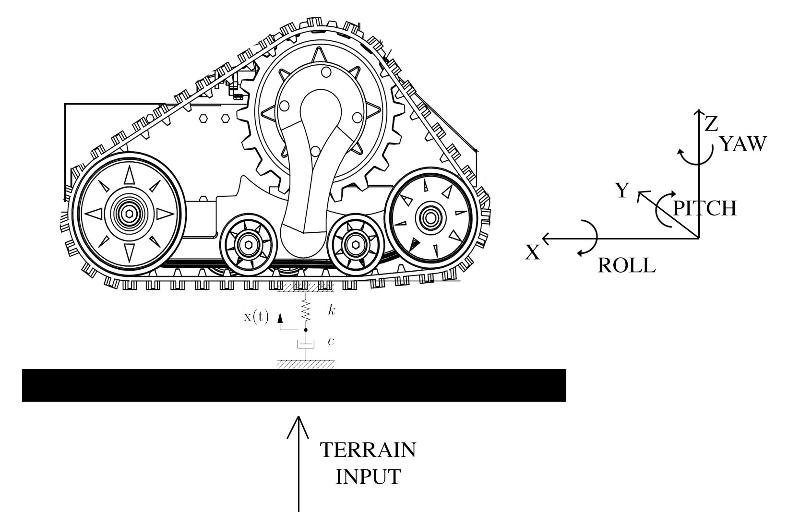
There are no suspensions, but I consider the rubber track as the combination of a spring, coefficient K, and a damper, coefficient b. The rubber compression is about Dx =1,5 mm
By supposing a sinusoidal input below the track generated by the terrain profile, u(t) = Asin(wt), I was able to write the equation for the Z axis:
Now, I would like to consider the lateral force Ft which acts on the robot during a turning motion.
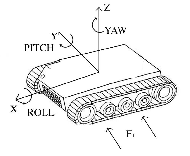
Let's consider the vehicle during a steering maneuver on the left: while the YAW angle changes to reach the target heading, the tracks are subjected to the later force as result of the terrain resistance.
Is there any way to write an equation to define the relation between the heading of the vehicle and the force Ft?
I do not know if you should consider the force Ft as a sine wave or a costant since it changes on if the vehicle sinks into the terrain.
I would like to write something like: Z(s) = G(s)X(s).
Can you suggest me how to write this relation, please?
track-robot.jpg
I would like to be able to write equations to model my tracked vehicle which has a mass m=200Kg.
My skid-steering vehicle uses one track per side with a rubber belt made in 100% natural rubber, please refer to the next photo to get a more detailed idea.

Since I mounted an IMU in its geometric center, I can read both the angular velocites and the accelerations along the three axis plus the heading, the pitch and yaw angles in degrees.
I would like to be able to write a model for the vehicle in order to simulate and study its outputs depending on specific inputs.
Each track has a length L=1000 mm, a width W=330 mm and a lug height, H = 32 mm.
The vehicle is Lv= 1000 mm long and Wv=900 mm width.
There are no suspensions, but I consider the rubber track as the combination of a spring, coefficient K, and a damper, coefficient b. The rubber compression is about Dx =1,5 mm
By supposing a sinusoidal input below the track generated by the terrain profile, u(t) = Asin(wt), I was able to write the equation for the Z axis:
X(s)/Y(S)=(bs+k)/((m/2)*s^2 + bs+k) for the right track
X(s)/Y(S)=(bs+k)/((m/2)*s^2 + bs+k) for the left trackNow, I would like to consider the lateral force Ft which acts on the robot during a turning motion.

Let's consider the vehicle during a steering maneuver on the left: while the YAW angle changes to reach the target heading, the tracks are subjected to the later force as result of the terrain resistance.
Is there any way to write an equation to define the relation between the heading of the vehicle and the force Ft?
I do not know if you should consider the force Ft as a sine wave or a costant since it changes on if the vehicle sinks into the terrain.
I would like to write something like: Z(s) = G(s)X(s).
Can you suggest me how to write this relation, please?
track-robot.jpg
ASKER CERTIFIED SOLUTION
membership
This solution is only available to members.
To access this solution, you must be a member of Experts Exchange.
ASKER
Thank you for your answer, Fred!!!
During the next days, I will try to implement a solution based on your suggestions and I will let you know! :)
During the next days, I will try to implement a solution based on your suggestions and I will let you know! :)
We will be interested to hear the results!
This looks to me like a very common six-degree of freedom set of equations - likely will be second-order.
The 6 degrees of freedom are: X, Y,Z,theta, phi, zeta where the last 3 are roll, pitch and yaw.
And, you would likely be considering X, X', X'' position, velocity and acceleration for each.
Surely you'll be doing a simulation in discrete time and not seeking some analytical solution.
Yet, you're showing a steady-state equation which isn't likely so flexible.
This critical decision will allow strange terrain profiles vs. steady-state or uniformly-varying profiles (like a sinusoidal surface).
You can write the simplest equations first that assume no cross-coupling. Not much fidelity in this but to imagine the others.
f=ma
a=f/m
X''=fx/m; X'=X'0 + at; X=X0+x't where "t" is time and you'd be using deltat for each time step in the simulation.
etc.
This will incorporate the external forces and compute the position and velocity in each degree of freedom.
The tricky part is determining the coefficients of second-order damping factors such as:
How much resistance or drag is there resulting from roll acceleration or roll velocity? etc.
Then you can have a more realistic model if you add cross-coupling terms:
e.g. forward velocity is an even function of yaw rate - the faster the vehicle turns, the more negative effect on forward velocity. It's "even" because it doesn't matter the direction of the yaw on the forward velocity.
Other terms will be "odd". Rotational drag depends on the direction of rotation - so it's and "odd" function of rotational velocity.
etc.
In terms of starting out, I'd get a set of fully-coupled 6DOF equations and then "trim" the cross-coupling coefficients according to what you think is unimportant or insignificant. For example, the rate of change of acceleration may not be important but the acceleration certainly is - so you limit the terms in the equations that way right off. The coupling of roll rate to
As far as the vehicle sinking, I've done this for water-skimming vehicles like yours using a simple f=ma model where "f" is the weight of the vehicle, "m" is the mass of the displaced liquid and "a" is gravity. You can calculate the vertical velocity due to gravity and fluid displacement and the vertical position due to displacement in a time step.
At each time step, you calculate the displacement until, for steady forward velocity, there is a constant depth.
It's the same as calculating the trajectory of a skipping stone without the skipping.
The weight of the object is the force. The density of the liquid provides the "drag" force. "m" is the mass of the liquid under the vehicle footprint.
I have a simple model in Excel for this one if it's of any interest.
I must admit that it's been a long time since I've done the full 6DOF models so I'd need to refresh my memory.