Connecting Cisco Switches to a Router
Connecting Cisco Switches to a Router
I just want to make sure the connection and ports configuration type is correct:
in the case we have Cisco Layer 3 Switches configured with VLANs and SVIs, we have Computers that are connected to the L3 Switches.
If I need the traffic on all L3 switches to be routed to a different Network, then I will have to bring an L2 switch and connected the uplink ports from all L3 switches to the ports on L2 Switch then bring a router and connect an uplink port from L2 switch to a Router.
the Uplink ports that connect L3 to L2 switches will be configured as Trunk Ports and the ports that connect L2 Swicth to the router will be configured as Trunk Ports.
Correct me if I am wrong
Thank you
ASKER CERTIFIED SOLUTION
membership
This solution is only available to members.
To access this solution, you must be a member of Experts Exchange.
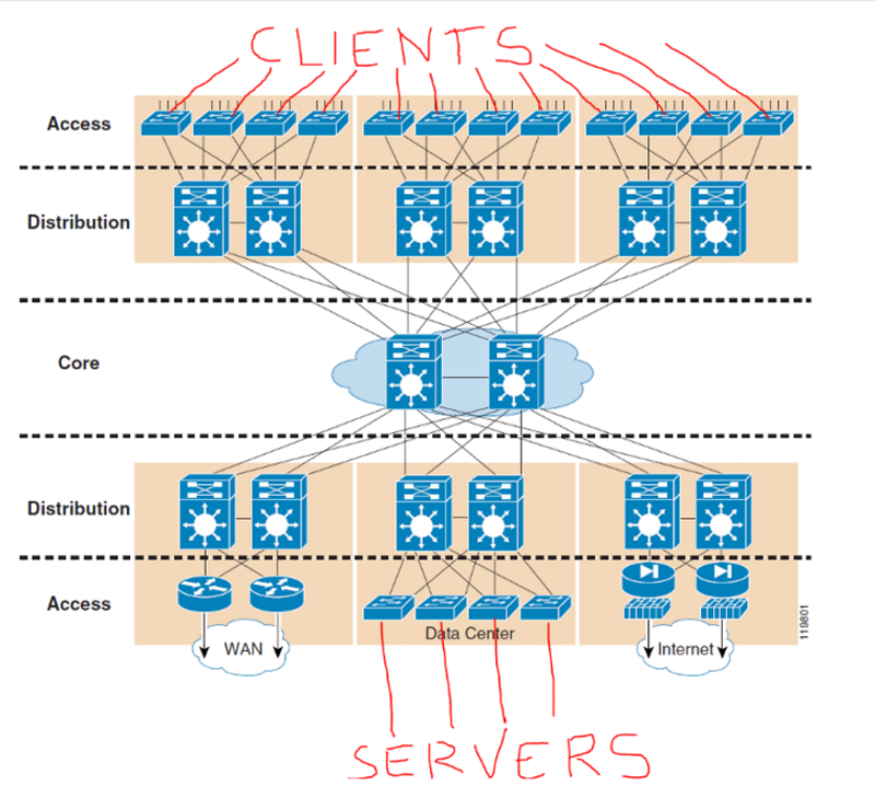
I've added a normal network design for the layers of the network. Hope this helps.
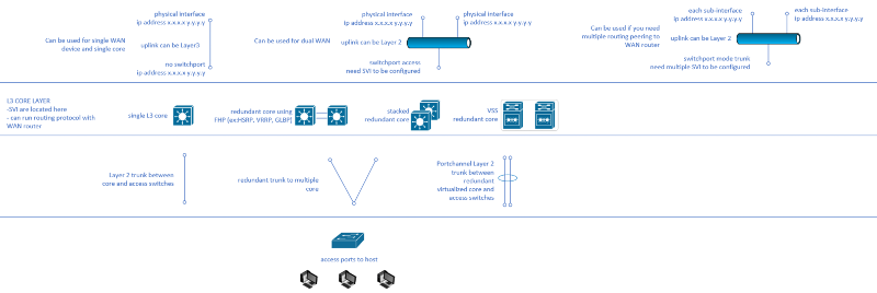
Do let us know if you are designing the network or if what you have described is an actual existing network, which you'd need to add some WAN connectivity.
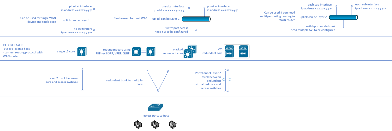
Do let us know if you are designing the network or if what you have described is an actual existing network, which you'd need to add some WAN connectivity.
ASKER
Sorry , I guess my approach mentioned in my Question above is is a little bit complex.
I believe the one below is much more simple.
The access Switches for Clients and Servers can be Layer 3 Switches with VLANs and SVI configured on them.
So if one client wants to talk to another client in a separated VLAN, but in the same switch , it will be able to do so without the traffic exiting the same L3 switch.
If a client wants to communicate with another client in different switches, then it can go through Distribution Switch [That uses VSS Technology].
The access Switches for Servers can be Layer 3 Switches with VLANs and SVI configured on them.
So if one Server wants to talk to another Server in a separated VLAN, but in the same switch , it will be able to do so without the traffic exiting the same L3 switch.
If a Server wants to communicate with another Server in different switches, then it can go through Distribution Switch [That uses VSS Technology].
If client wants to communicate with a Server then it will go through Distribution Switch to Core Switch to Distribution Switch then to the Server.
jsk -
Unless you are going to change the default gateway for all hosts connecting to your access layer, all your traffic processing between VLANs/Subnets, will be switched at the core.
VSS is for interconnecting two 45/65xx series switches to present as one logical device to the rest of the network. Think of it like Catalyst Stackwise or Nexus VPC. Not sure what you're expectations are in using this but you need to make sure that you understand what it does and does not do, what it can and cannot do.
My previous comments still apply.
ASKER
Let's look at it one Section at a Time.
If Client 1 and Client 2 both are in Building A same floor , 2 different Vlans
If client 1 wants to to communicate to Client 2 and they are both in different VLANs, should the traffic go all the way to the Core switch that might be completely in different Building and come back to Client 2 ?
I believe connecting Clients to L3 Switches , then Trunking L3 Switches to Distributed Switch [that should be in the same Building] make it easier.
That way Clients traffic will travel to Core only if it needs to communicate with Servers or with Clients that are on the L3 Access Switches but that are not hanging off the same Distribution Switch
I guess the question that I would ask is; what is the impediment or impediments that you perceive with having the traffic travel the extra distance?
So here are the problems that I see with the proposed build in the immediate:
1. Assuming that routing works the way you want it to; how are your planning on handling addressing? If you want to use DHCP you are going to have to build a DHCP server in each distribution segment. This will be necessary to insure that you are able to get the correct default gateway for that particular segment (the DFG would be the SVI of the homed distro switch). Otherwise, you are stuck with statically assigning IP information on each individual host.
2. The reason I say assuming routing works. You are proposing to stand up multiple SVI's and then have them route from switch to switch. First problem, if I understand your idea right - you want to build a VLAN with an underlying /24 subnet. You then want to place an SVI on each of the distribution switches for this VLAN. So on switch 1 we will say the SVI is .1, on Switch 2 .2, 3- .3, 4- .4 and so on. You want traffic internal to a particular VLAN but destined for a host on a different distribution switch (lets say host 1a on sw 1 destined for host 3b on switch 3) to come up to the local SVI, be routed to the SVI of the remote switch and then forwarded to the remote host. In other words:
Host 1A@192.168.1.11/24 destined for Host 3B@192.168.1.31/24 should come up to SVI .1, is switched to .3 and then forwarded down. Do you see the problem in this? .11 is going to see .31 as local to itself. It will never ARP for the gateway and forward (its not logically remote). But - assuming you have all VLANs are on all switches and all switches are connected via trunks and not layer 3 interconnects, what will happen is Host1A will ARP for Host 3B. This broadcast will go to all ports on VLAN X. Host 3B will see the ARP and then unicast back to 1A. 1A will then beginning forwarding. Looking at your topology from a layer 2 perspective, the traffic still goes up to the core and then back down.
Thats all for intra-vlan traffic.
What about Inter-vlan? Again, where/what is the default gateway for a given local vlan segment. If it is pointing to the local SVI, traffic will go up and then go......where? If you are using the SVI's on each of the local switches, which SVI does it get forwarded to? How to resolve? Static routing, which is going to static routing. You can do one of two things here. You can statically configure a /32 host route on each switch for each host in the network or you can subnet. Example one? You will most likely throw yourself into a wood chipper in the near future. Example 2? What are you listing the same VLAN on multiple switches with different subnets? Additionally, what happens if traffic ever gets to the core? My bet is the core is going to meltdown - and you with it.
If you want to get the type of direct connectivity you are hinting at above, you have some layer 1 work to do and then leverage layer 2. But - before you go that route, answer my question at the very beginning of the post.
ASKER
atlas_shuddered
My main goals is to understand:
the command Design used in real world when you have a Data Center in One Building and Client computers in other Buildings Surrounding the Data Center. ?
My main goals is to understand:
the command Design used in real world when you have a Data Center in One Building and Client computers in other Buildings Surrounding the Data Center. ?
The long and short is to co-locate like hosts as much as possible. Then VLAN and let layer 2 do what it does. Bring servers, services and apps into the datacenter (this is what it is for - housing critical items and providing increased resilience and availability). Move into layer 3 as necessary (introduction of higher layer serviceability, intra-segment transfer/routing, etc.)
Services/Awareness - Increased Latency
/\
|
|As you move up or down the stack in a network
|you will move toward and away from benefits
|
\/
Speed/Extensibility - Lower Visibility on the path/Loss of Customization/Control
That all noted, don't let it fool you, the subject matter is no small thing and there is a ton to learn toward success.
ASKER
I meant Physical Design , I believe the Diagram I posted , Should be good, except that I am not sure if the Switches the clients are connected to should be L2 or L3
On each Building we'll have 2 Distribution switches that use VSS Technology ,
for instance
Build A will have all clients connected to L2 Switches and L2 Switches connect to Distribution Switches
Build B will have all clients connected to L2 Switches and L2 Switches connect to Distribution Switches
Build C will have all clients connected to L2 Switches and L2 Switches connect to Distribution Switches
Distribution Switches will connect to CORE switches
The other side [Servers] will be the same too, they will connect to L2 Switches --->Distribution --->CORE
The SVI can be on Distribution or Core...Not sure which option is better..
The physical design is reasonable. As to whether you want to access @ layer 2 or 3, I would default to the access switches being configured at layer 2. Configuring at layer 3, as I noted above, is going to add in complexity that may not get you any gain. If traffic is all trusted and there are no real boundary issues besides traffic managment, then stay layer 2. If you are going to say that you need traffic inspections and enforcements between segments, then layer 3 may be a legitimate need.
ASKER
the only reason I thought about Layer 3, is to do Routing right there on the Access Switches instead of being done at the Distribution switch or Core Switches that might be a distance away
Again, you can do that but it is going to impact your VLANs, subnetting and network addressing/path management.
Hi jskfan,
Just like to share some more ideas from my experience at work. Normally our local sites would look like this.
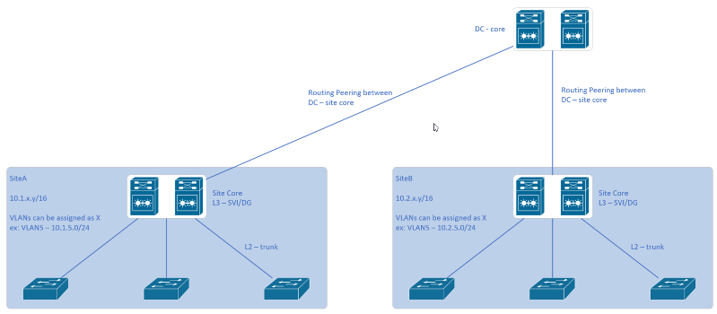
Just like to share some more ideas from my experience at work. Normally our local sites would look like this.
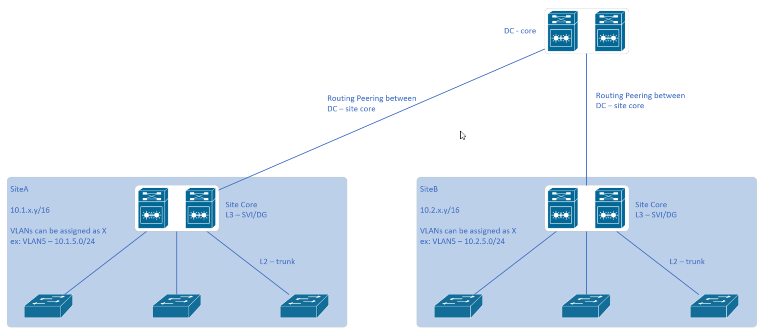
- Each site has their "core" switch which acts as the SVI or default gateway for all the VLANs trunked down to the access switches. (your term for this was distribution switch)
- Communication between inter-VLANs on the same site are routed by the site core switch
- Normally we assign the private address block 10.s.v.x/16 per site. "s" represents the site, like site 1, site 2, site 3. "b" represents the VLAN.
- In this case we can standardize, like VLAN5 is dedicated for servers. For example, 10.2.5.x/24 represents something at site-2 server VLAN5. You can extend this idea with your clients that are multisite.
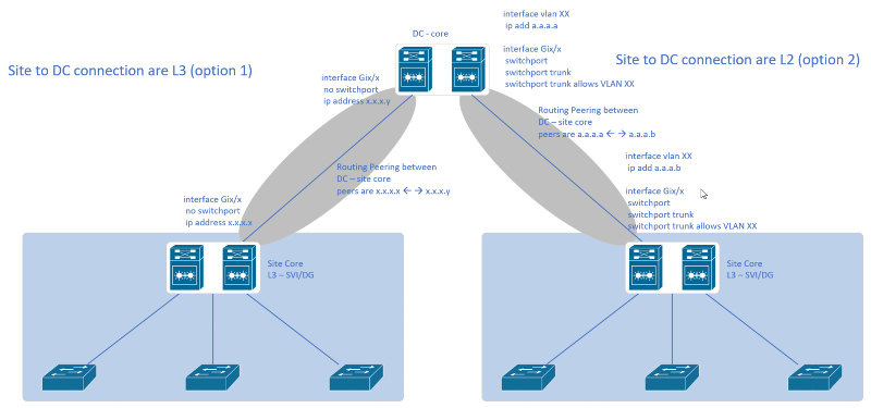
- Between the site core and the DC core is a routing peering. Now this interconnection can be L2 or L3 as I'll illustrate below and discuss each one.
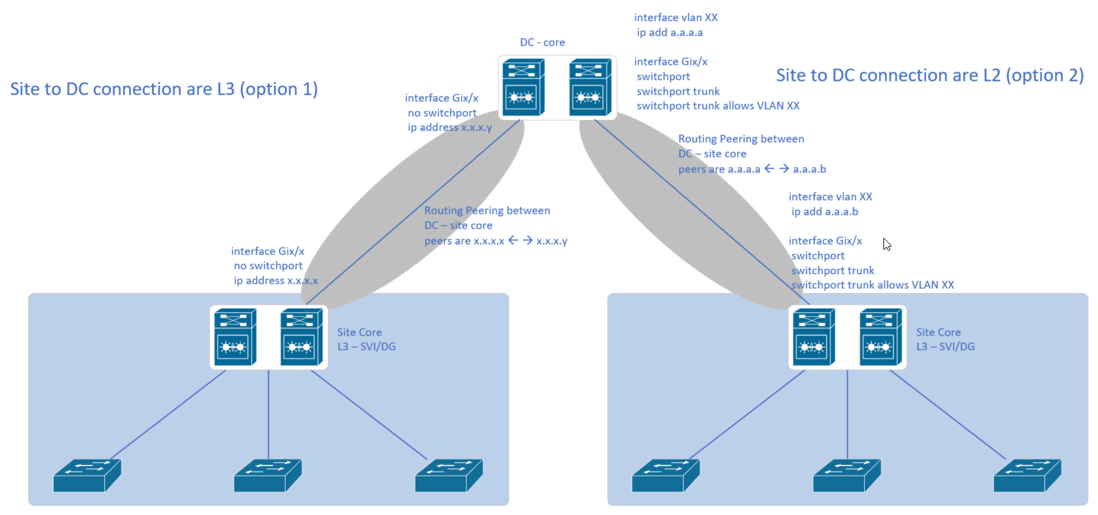
- Option1 on the left is just a straight up layer 3 interface between site-core and the DC-core. Routing peering is between the L3 interfaces. We prefer this option over the other.
- With option 2, the routing peering is between the VLAN SVI created at each of the cores. The downside of this is that basically you'll be extending VLAN domains from site to the DC-core. I wouldn't recommend this setup.
ASKER
Nico Eisma
Thanks for The Diagram and Explanation.
if you can elaborate a little bit on Option 2 [Site to DC Connection are L2]
I see you configured Trunk ports on Distribution Switch and Core Switch , what is that for ?
what about that SVI [Interface Vlan XX] , what is it for ? since the Ports are Trunk Ports.
Option 1
makes more sense to me.
All VLANs traffic within a site is routed at the Distribution Switch, if the traffic needs to go to different site it will be routed from Distribution Switch to Core Switch, and the Core Switch will route to whatever Site [Distribution Switch] it is going to.
Thank you
jsk -
Option 2 is a hybridized model. Layer 2 throughout with routing at the distribution layer using SVI. Again, this is usable as long as you understand how it impacts your vlan schema, subnetting, etc. Having said that, it looks like your goals are changing now. As noted above, if you are going to run isolated vlans at each of the buildings, then having your layer at the building is workable but again, if you want to commonize vlans and have them span multiple buildings, you will need to run true layer 2 back to your core.
Option 2 is a hybridized model. Layer 2 throughout with routing at the distribution layer using SVI. Again, this is usable as long as you understand how it impacts your vlan schema, subnetting, etc. Having said that, it looks like your goals are changing now. As noted above, if you are going to run isolated vlans at each of the buildings, then having your layer at the building is workable but again, if you want to commonize vlans and have them span multiple buildings, you will need to run true layer 2 back to your core.
Hello jskfan,
Let me try and present it visually as shown below.

To comment on your questions
Again, I would caution in using this kind of approach as atlas_shuddered explained above.
Just a few personal note:
Hopefully these inputs gave you the information you need and have helped you understand the topic better.
Let me try and present it visually as shown below.
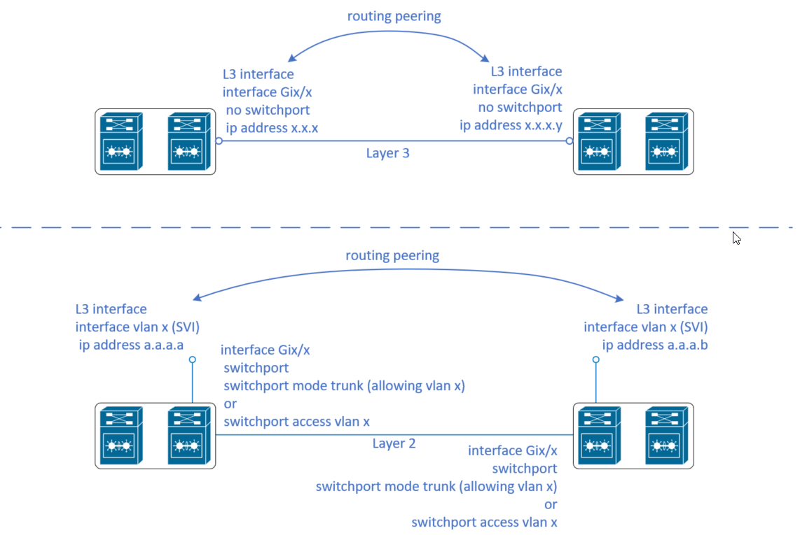
To comment on your questions
- Basically below you'd notice that the routing peering is established between the SVI, compared to above where the routing peering is established between the L3-interfaces
- The ports connecting the two devices are basically running at Layer 2. As such, it can be configured as a trunk port where VLAN x is being allowed on the trunk or as an access port assigned VLAN X. Either way it should work.
Again, I would caution in using this kind of approach as atlas_shuddered explained above.
Just a few personal note:
- Using option 2 extends a VLAN between the DC and the site. This defeats the purpose of isolating each site in their own VLAN domain and L3 domain (subnet). Additionally, this will not only extend VLAN domains it will also extend STP domains between the DC and site.
- Routing protocols peer loss detection and convergence also differs in the two setup. I'd link you to a great article below to expound on the details on this.
Hopefully these inputs gave you the information you need and have helped you understand the topic better.
ASKER
-- So Access Switches will be Layer 2.
-- VLANs preferrably stay on the same site do not span to other site
-- create SVIs on Distribution Switches on each site, they will be used as Default Gateway for computers on their Site.
--- IP routing will be configured on Distribution Switches on each site to route traffic between computers on that site
--- Also configure IP on ports between Distribution Switches and Core Switche Ports

yes
ASKER
Thank you very much Guys for the explanation !
You would use your layer 3 switches to do any routing between local subnets and only use the router as a gateway between local networks and any remote networks.
Your connection between the router and the layer 3 switch could be accomplished in one of two ways:
1. A layer 3 interface on the switch connected to the router in a /30 local link connection
2. The router connected via access port to a particular vlan on the layer 3 switch. If you do this, it would be best to build a routing/layer 3 vlan so you can keep the networking somewhat clean.
In either case, you would have the local hosts point to the SVI in each of the vlans for their default gateway. You would then build a default route on the layer 3 switch pointing to the router.