Rocco Galati
asked on
Extract x,y points from DWG file with a C++ library
I'm developing a path following application for my robot in order to make it move towards some x,y points in a map.
The points are contained in a DWG file, so I need to find out a way to extract them and use them as navigation waypoints.
I'm using libopencad in C++ since I would like to export the coordinates about the shapes contained in a standard DWG file.
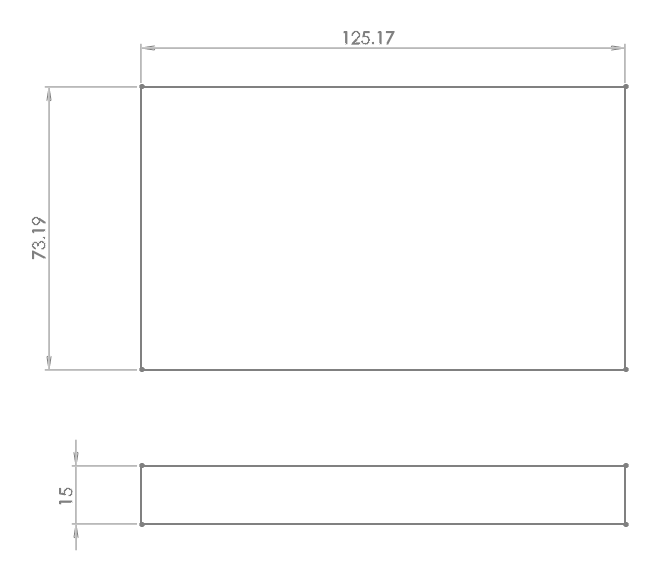
Let's say that I have a DWG file which contains two rectangles:
By using the cadinfo.cpp sample file, I'm successfully able to open the DWG file and extract the coordinates of each line that belongs both rectangles.
The problem is: how can I understand what are the coordinates that belong to the first rectangle and the coordinates that belong to the second one?
Moreover, there can be more than two rectangles in each DWG file.
The points are contained in a DWG file, so I need to find out a way to extract them and use them as navigation waypoints.
I'm using libopencad in C++ since I would like to export the coordinates about the shapes contained in a standard DWG file.
Let's say that I have a DWG file which contains two rectangles:
By using the cadinfo.cpp sample file, I'm successfully able to open the DWG file and extract the coordinates of each line that belongs both rectangles.
Layers count: 1
1. Layer 0 contains 8 geometries
|---------Line---------|
Start Position:     62.5852 -36.5942    0
End Position:   -62.5852    -36.5942    0

Entity color: #ffffffff
|---------Line---------|
Start Position:     62.5852 -36.5942    0
End Position:   62.5852 36.5942 0

Entity color: #ffffffff
|---------Line---------|
Start Position:     62.5852 36.5942 0
End Position:   -62.5852    36.5942 0

Entity color: #ffffffff
|---------Line---------|
Start Position:     -62.5852    -36.5942    0
End Position:   -62.5852    36.5942 0

Entity color: #ffffffff
|---------Line---------|
Start Position:     62.5852 -76.4212    0
End Position:   -62.5852    -76.4212    0

Entity color: #ffffffff
|---------Line---------|
Start Position:     62.5852 -76.4212    0
End Position:   62.5852 -61.4214    0

Entity color: #ffffffff
|---------Line---------|
Start Position:     62.5852 -61.4214    0
End Position:   -62.5852    -61.4214    0

Entity color: #ffffffff
|---------Line---------|
Start Position:     -62.5852    -76.4212    0
End Position:   -62.5852    -61.4214    0

Entity color: #ffffffffThe problem is: how can I understand what are the coordinates that belong to the first rectangle and the coordinates that belong to the second one?
Moreover, there can be more than two rectangles in each DWG file.
@Rocco Galati
Replace:
if( pszErrorMsg != nullptr )
...
else if(argc == 1)
With:
if( nullptr != pszErrorMsg )
...
else if ( 1 == argc )
All conditional checking:
Reason:
if we miss one equal character while writing == operator,
Original
if (pCADFile == nullptr)
Error:
if (pCADFile = nullptr)
nullptr assigned to pCADFile and then validate if statement.
if ( nullptr == pCADFile )
When using
if ( nullptr = pCADFile )
compiler will report related error.
Write value at left side of operator and variable at right side of operator
if ( 10 == VariableName )
Report error can happen when we get enhancement/new requirements and modifying existing code.
As per the comment from Sara
top left = (-62.582, 36.5942)
top right = (+62.582, 36.5942)
bottom right = ( 62.582, -36.5942)
bottom left = (-62.582, -36.5942)
Same thing using pixel location at X/Y axis => like the way we have used using X/X/Z at 3D.
|
a |36.5942 b
Top Left | top right
-62.582, +36.5942 | +62.582, +36.5942
|
|
--------------------------
-62.582 | +36.5942
|
|
c | d
bottom left |-62.582 Bottom right
-62.582 -36.5942 | +62.582, -36.5942
|
if we miss one equal character while writing == operator,
Murugesan, any c/c++ compiler since c++ standard from 1998 would give at least a warning if you were using assign operator = instead of comparison operator == .
so it is quite ok to using a variable as left operand and a constant as right operand when using operator== in an if or loop condition.
moreover, doing so improves the readability of the statement since it is the way humans would express conditions when talking together, nobody says "I will apologize because wrong I was". it would be a mistake and would make it difficult to understand what you wanted to say at all. same happens to me when i was reading "wrong" conditional order of operands for the sake of a bygone compiler deficiancy.
Sara
p. s. you also should consider that the first part of your answer is off-topic in this thread as it doesn't add anything to the solution.
ASKER
Thank you for your answers and your feedback!
My initial question was not very clear, I'm sorry for this.
I know that the x,y coordinates provided by the C++ code refer to the start and end point of each line (we have in total 8 2-dimensional points since we have two rectangles.
The problem is that in order to optimize the path, I want to make the robot to move along all the vertical lines and then along all the horizontal lines.
Since the robot paints on the floor, it is better to paint before all the vertical lines and then all the horizontal ones.
I can use each corner point as a waypoint and it is really great, but the problem is:
how can I automatically load all the coordinate that belong to the vertical lines and then the coordinates that belong to the other ones?
The code I developed for my robot works in this way:
1. receive a pair of 2d coordinates
2. move along the X axis until it reaches the correct X value
3. move straight along the Y axis until it reaches the desired Y value
4. it communicates that the goal is accomplished and is ready for the next pair of coordinates
The code works fine when I test it with only one x,y point:
P.S. my robot can move sideway.
Should I load the coordinates in a 2 dimensiona array? Or should I use a class or a structure?
and how can I couple them?
let's consider this DWG:
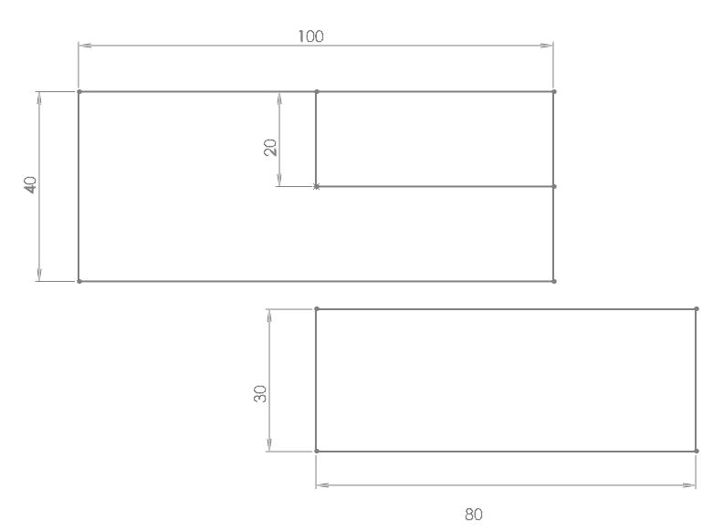
which provides this output:
This figure is more complex even if it is more close to the real world case.
My initial question was not very clear, I'm sorry for this.
I know that the x,y coordinates provided by the C++ code refer to the start and end point of each line (we have in total 8 2-dimensional points since we have two rectangles.
The problem is that in order to optimize the path, I want to make the robot to move along all the vertical lines and then along all the horizontal lines.
Since the robot paints on the floor, it is better to paint before all the vertical lines and then all the horizontal ones.
I can use each corner point as a waypoint and it is really great, but the problem is:
how can I automatically load all the coordinate that belong to the vertical lines and then the coordinates that belong to the other ones?
The code I developed for my robot works in this way:
1. receive a pair of 2d coordinates
2. move along the X axis until it reaches the correct X value
3. move straight along the Y axis until it reaches the desired Y value
4. it communicates that the goal is accomplished and is ready for the next pair of coordinates
The code works fine when I test it with only one x,y point:
  geometry_msgs::Point p;
  n.getParam("/base_planner/x", p.x);
  n.getParam("/base_planner/y", p.y);
  while(n.ok()){
   ...
    prev_x = p.x - x;
    prev_y = p.y - y;
  ...
}P.S. my robot can move sideway.
Should I load the coordinates in a 2 dimensiona array? Or should I use a class or a structure?
and how can I couple them?
let's consider this DWG:
which provides this output:
Named Object Dictionary records:

Layers count: 1
1. Layer 0 contains 11 geometries
|---------Line---------|
Start Position: 	-3.85186e-31	20	0
End Position: 	0	0	0

Entity color: #ffffffff
|---------Line---------|
Start Position: 	50	-20	0
End Position: 	-50	-20	0

Entity color: #ffffffff
|---------Line---------|
Start Position: 	50	-20	0
End Position: 	50	20	0

Entity color: #ffffffff
|---------Line---------|
Start Position: 	50	20	0
End Position: 	-50	20	0

Entity color: #ffffffff
|---------Line---------|
Start Position: 	-50	-20	0
End Position: 	-50	20	0

Entity color: #ffffffff
|---------Line---------|
Start Position: 	0	0	0
End Position: 	50	0	0

Entity color: #ffffffff
|---------Line---------|
Start Position: 	-3.67394e-15	-25.8654	0
End Position: 	80	-25.8654	0

Entity color: #ffffffff
|---------Line---------|
Start Position: 	-3.67394e-15	-25.8654	0
End Position: 	0	-55.8654	0

Entity color: #ffffffff
|---------Line---------|
Start Position: 	0	-55.8654	0
End Position: 	80	-55.8654	0

Entity color: #ffffffff
|---------Line---------|
Start Position: 	80	-25.8654	0
End Position: 	80	-55.8654	0

Entity color: #ffffffff
|---------Point---------|
Position: 	0	0	0

Entity color: #ffffffffThis figure is more complex even if it is more close to the real world case.
@Rocco Galati
Better use struct (for data) and class(for actions) since data being dynamic
>> P.S. my robot can move sideway.
>> how can I couple them?
each block at linked list having (x/y) co-ordinates.
I am not having libopencad
We can achieve the same using related compilers at any OS
AIX => xlC
HP-UX => CC or aCC
IRIX => c++
CYGWIN_NT => g++ or g++.exe or c++ or c++.exe
Linux => g++ or c++
NonStop => CC
OSF1 => cxx
SunOS => CC
UNIX_SV => ec++
>> any c/c++ compiler since c++ standard from 1998 would give at least a warning
Do not depend completely on compiler warning message:
Assume that we have twenty thousand source code and single Makefile
make command going to each directory and complining
difficult to find the warning message when more source code changes has been approved by supervisor.
Sample code for warning message:
Hence re-compiled to get assembler output
Stop after the preprocessing stage
; 1;
is of no use
Hence obtaining the warning:
warning: statement has no effect
>> Do not depend completely on compiler warning message
Also use
-g option during compilation
or gdb
or gdb.exe based on OS
Sample gdb tutorial
https://www.tutorialspoint
However when releasing final code we can
1. either remove -g option
2. or use -ggdb3
Proceed above steps based on deployment guide prepared by development team.
Better use struct (for data) and class(for actions) since data being dynamic
>> P.S. my robot can move sideway.
>> how can I couple them?
each block at linked list having (x/y) co-ordinates.
I am not having libopencad
We can achieve the same using related compilers at any OS
AIX => xlC
HP-UX => CC or aCC
IRIX => c++
CYGWIN_NT => g++ or g++.exe or c++ or c++.exe
Linux => g++ or c++
NonStop => CC
OSF1 => cxx
SunOS => CC
UNIX_SV => ec++
>> any c/c++ compiler since c++ standard from 1998 would give at least a warning
Do not depend completely on compiler warning message:
Assume that we have twenty thousand source code and single Makefile
make command going to each directory and complining
difficult to find the warning message when more source code changes has been approved by supervisor.
Sample code for warning message:
$ cat ./29177556_warning.c
// UNIT TESTING FOR WARNING MESSAGE
#include <iostream>
using namespace std;
int main()
{
        int max = 0;
        max = MAX( 2020, 2021);
        cout << max << '\n';
        return 0;
}$ g++ -Wall -D "MAX( A, B) ( A > B ? A: B);" ./29177556_warning.c -o ./a.out
./29177556_warning.c: In function ‘int main()’:
./29177556_warning.c:7:24: warning: statement has no effect [-Wunused-value]
max = MAX( 2020, 2021);Hence re-compiled to get assembler output
Stop after the preprocessing stage
$ g++ -E -Wall -D "MAX( A, B) ( A > B ? A: B);" ./29177556_warning.c | tail
}
# 3 "./29177556_warning.c" 2
using namespace std;
int main()
{
 int max = 0;
 max = ( 2020 > 2021 ? 2020: 2021); 1;
 cout << max << '\n';
 return 0;
}; 1;
is of no use
Hence obtaining the warning:
warning: statement has no effect
>> Do not depend completely on compiler warning message
Also use
-g option during compilation
$ g++ -g -Wall -D "MAX( A, B) ( A > B ? A: B);" ./29177556_warning.c -o ./a.out
./29177556_warning.c: In function ‘int main()’:
./29177556_warning.c:7:24: warning: statement has no effect [-Wunused-value]
max = MAX( 2020, 2021);or gdb
or gdb.exe based on OS
$ gdb -q ./a.out
Reading symbols from /home/murugesandins/experts_exchange/a.out...done.
(gdb) break main
Breakpoint 1 at 0x400738: file ./29177556_warning.c, line 6.
(gdb) run
Starting program: /home/murugesandins/experts_exchange/a.out

Breakpoint 1, main () at ./29177556_warning.c:6
6               int max = 0;
(gdb) next
7               max = MAX( 2020, 2021);
(gdb) next
8               cout << max << '\n';
(gdb) continue
Continuing.
2021

Program exited normally.
(gdb) quitSample gdb tutorial
https://www.tutorialspoint
However when releasing final code we can
1. either remove -g option
2. or use -ggdb3
Proceed above steps based on deployment guide prepared by development team.
ASKER
@Murugesan N: thank you for your support, but I cannot understand how the gdb answer is related to my main topic.
Can you explain it better, please?
Can you explain it better, please?
@Rocco Galati
>> what are the coordinates that belong to the first rectangle and the coordinates that belong to the second one
use -g option to compile the program
using gdb
gdb ./a.out
break 100
Assume that you are assigning coordinates at line number 100
Assume that the variable a,b,c are assigned at 100, 101, 102 lines
Sample at my system:
"next" at gdb provide following details:
and exit gdb
When you do gdb again
after reach the same location
type "step" instead of "next"
Hene given previously gdb tutorial url.
GNU project debugger gdb
digital branch exchange dbx
I like gdb than dbx (and used gdb related alias inside dbx not now before 2013 )
>> what are the coordinates that belong to the first rectangle and the coordinates that belong to the second one
use -g option to compile the program
using gdb
gdb ./a.out
break 100
Assume that you are assigning coordinates at line number 100
Assume that the variable a,b,c are assigned at 100, 101, 102 lines
Sample at my system:
$ grep -n $ gdb_learn.c
1:#include <iostream>
2:using namespace std;
3:int main(int argc, const char** argv)
4:{
5:      short x = 1;
6:      short y = 2;
7:      short z = 3;
8:      while ( 1 )
9:      {
10:             x = x+1;
11:             y = y+1;
12:             z = z+1;
13:             if ( 0 == x )
14:             {
15:                     cout << "x value is zero\n";
16:                     x = x + 12;
17:                     cout << "x value " << x << '\n';
18:                     break;
19:             }
20:     }
21:}
$ g++ -g -Wall gdb_learn.c -o ./a.out
$ gdb -q ./a.out
Reading symbols from /home/murugesandins/experts_exchange/a.out...done.
(gdb) break 15
Breakpoint 1 at 0x4007ea: file gdb_learn.c, line 15.
(gdb) run
Starting program: /home/murugesandins/experts_exchange/a.out

Breakpoint 1, main (argc=1, argv=0x7fffffffe618) at gdb_learn.c:15
15                              cout << "x value is zero\n";
(gdb) step
x value is zero
16                              x = x + 12;
(gdb) next
17                              cout << "x value " << x << '\n';
(gdb) continue
Continuing.
x value 12

Program exited normally.
(gdb) quit"next" at gdb provide following details:
(gdb) n
Invalid binary operation on numbers.and exit gdb
When you do gdb again
after reach the same location
type "step" instead of "next"
Hene given previously gdb tutorial url.
GNU project debugger gdb
digital branch exchange dbx
I like gdb than dbx (and used gdb related alias inside dbx not now before 2013 )
>> thank you for your support,
welcome and let us know your query if any ?
welcome and let us know your query if any ?
ASKER CERTIFIED SOLUTION
membership
This solution is only available to members.
To access this solution, you must be a member of Experts Exchange.
@Rocco:
You main function is too long, and it is a catch-all function (in other words, it break the SRP principle), it should b broken into several smaller functions that do one thing, and do it well. At least, you should have:
- Analyse command lines arguments.
- Read the CAD file.
- Compute data.
- Display results.
Give up defensive programming, it is unproductive, use assertions to check for functions parameters, your application will crash if a wrong parameter is given to a function, denoting a programming error that you must fix.
Don't use the "using namespace std" directive, the sole purpose of this directive is to ensure STL's compatibility with minimal efforts to old code (prior 1998), plus as a side effect, you're polluting the global namespace.
Use std::string data type as much as you can instead of old troublesome C-like string arrays (char raw pointers)
Raw pointers have many issues, I won't enumerate them here.
(as a general advice, use STL's data type as much as you can).
Don't pre-declare you variables, it increase it's life time longer than needed.
Definetly use data structures or class to represent the concepts you are handling.
Concerning your issue, checking if a line is horizontal or vertical, it is simple enough knowing the the coordinates of its extremities:
If the abscissa (x) of both points are equal, the line is vertical.
If the ordonate (y) of both points are equal, the line is horizontal.
If both abscissa and ordonate differ, it is none of the above.
ASKER
Thank you for your support.
I'm a Roboticist and so, unfortunately, I'm not a C++ programmer, for this reason it is not so easy for me to figure out how to modify the code to get what I need.
At the moment, I spent all the day to try to modify the class CADGeometry and CADLine in order to add a function that load in a array all the X and Y values so I can pass them to my planner code, but at the moment I wasn't able to.
Leave the CADGeometry and CADLine classes alone, you did not wrote them.
Rule of thumb:
If a concept is too tough to handle, split it into smaller concepts.
What do you need to handle ? Rectangles
What is a rectangle ? It is four points.
What is a point ? It is 2 coordinates: x and y.
So here we go, write a point class, then a rectangle class holding 4 points.
Next, think about the services your classes need to provide, that will be the member functions of your classes.
Finally, since your file hold many (quantity unknown) rectangles, you'll need a container to store them, the STL libray provide a great container for this purpose: std::vector.
ASKER
yes, I was already going with this solution but in order to populate the vector I need to store the x and y values obtained by using the DWG library I posted before.
I found out that the coordinates are printed by print() function which is declared in CADGeometry() class and it is overriden by CADLine() in CADGeometry.h and CADGeometry.cpp.
I have to find a way to store the values returned by start.getposition.getX() and start.getposition.getY() in my array.
I found out that the coordinates are printed by print() function which is declared in CADGeometry() class and it is overriden by CADLine() in CADGeometry.h and CADGeometry.cpp.
I have to find a way to store the values returned by start.getposition.getX() and start.getposition.getY() in my array.
ASKER
To be more specific, the main() code prints the line coordinates here:
and print() is implemented in CADGeometry.cpp
So, I should get be able to store the start.getPosition().getX()
Moreover, I cannot understand how print() function can access to start.getPosition().getX()
I'm sorry if my question is stupid, but I'm not expert in C++ and this library uses very complex classes.
        for ( j = 0; j < layer.getGeometryCount (); ++j )
        {
            unique_ptr<CADGeometry> geom(layer.getGeometry (j));

            if ( geom == nullptr )
                continue;

            if(!bSummary)
            {
geom->print();and print() is implemented in CADGeometry.cpp
void CADLine::print() const
{
    cout << "|---------Line---------|\n" << "Start Position: " << "\t" << start.getPosition().getX() << "\t" <<
    start.getPosition().getY() << "\t" << start.getPosition().getZ() << "\n" << "End Position: " << "\t" <<
    end.getPosition().getX() << "\t" << end.getPosition().getY() << "\t" << end.getPosition().getZ() << "\n" << endl;
}So, I should get be able to store the start.getPosition().getX()
class CADGeometry
{
public:
    CADGeometry();
    virtual ~CADGeometry();
    /**
     * @brief The CAD geometry types enum
     */
    enum GeometryType
    {
        UNDEFINED = 0,
        POINT,
        CIRCLE,
        LWPOLYLINE,
        ELLIPSE,
        LINE,
		POLYLINE2D,
        POLYLINE3D,
        TEXT,
        ARC,
        SPLINE,
        SOLID,
        RAY,
        HATCH, // NOT IMPLEMENTED
        IMAGE,
        MTEXT,
        MLINE,
        XLINE,
        FACE3D,
        POLYLINE_PFACE,
        ATTRIB,
        ATTDEF
    };

    enum GeometryType getType() const;
    double            getThickness() const;
    void              setThickness( double thicknes );
    RGBColor          getColor() const;
    void              setColor( RGBColor color );// TODO: in 2004+ ACI is not the only way to set the color.

    vector<CADAttrib> getBlockAttributes() const;
    void              setBlockAttributes( const vector<CADAttrib>& value );

    vector<string> getEED() const;
    void           setEED( vector<string> eed );

    virtual void print() const                     = 0;
    virtual void transform( const Matrix& matrix ) = 0;
protected:
    vector<CADAttrib> blockAttributes; // attributes of block reference this geometry is attached to.

    vector<string>    asEED;
    enum GeometryType geometryType;
    double            thickness;
    RGBColor          geometry_color;
};

...
class CADLine : public CADGeometry
{
public:
    CADLine();
    CADLine( const CADPoint3D& startIn, const CADPoint3D& endIn );

    CADPoint3D getStart() const;
    void       setStart( const CADPoint3D& value );

    CADPoint3D getEnd() const;
    void       setEnd( const CADPoint3D& value );
    virtual void print() const override;
    virtual void transform( const Matrix& matrix ) override;
protected:
    CADPoint3D start;
    CADPoint3D end;
    };
Moreover, I cannot understand how print() function can access to start.getPosition().getX()
I'm sorry if my question is stupid, but I'm not expert in C++ and this library uses very complex classes.
ASKER
Leave the CADGeometry and CADLine classes alone, you did not wrote them.@Fabrice Lambert: sorry, i haven't read your comment before to post. I would like to avoid to use that classes, but without them, how can I extract the lines from the DWG file?
I do not know other methods that can be used to read and extract such information for a DWG file.
I think I'm forced to rely on this classes for my program even if my main goal is to have a very simple application which does just what I need without anything else.
@Rocco Galati
>> I cannot understand how print() function can access to start.getPosition().getX()
My comment may be out of scope.
If compiled using -g option and using gdb we can insert a break point for function also:
I have written only sample code:
Hence using gdb we can print the value of any pointer or variables inside gdb
ptype to know the data type.
Hence given earlier => [b]Sample gdb tutorial[/b] => gdb.
If possible => Can you post your code at zip/gz files ?
>> I cannot understand how print() function can access to start.getPosition().getX()
My comment may be out of scope.
If compiled using -g option and using gdb we can insert a break point for function also:
I have written only sample code:
#include <iostream>
using namespace std;
class base
{
	public:
		base();
		virtual ~base();
		virtual void basefun();
};
base::base()
{
}
base::~base()
{
}
void base::basefun()
{
	cout << "basefun\n";
}
class derived:public base
{
	public:
		derived();
		virtual ~derived();
		void derivedfun();
};
void derived::derivedfun()
{
	basefun();
	cout << "derivedfun\n";
}
derived::derived()
{
}
derived::~derived()
{
}
int main( int argc, const char ** argv)
{
	derived d;
	d.derivedfun();
	return 0;
}$ /usr/bin/g++ -g -Wall -std=c++11 ./sample.cpp -o ./a.out
$ gdb -q ./a.out
Reading symbols from /home/murugesandins/experts_exchange/29177556/a.out...done.
(gdb) break derived::derivedfun
Breakpoint 1 at 0x400964: file ./sample.cpp, line 29.
(gdb) run
Starting program: /home/murugesandins/experts_exchange/29177556/a.out
Breakpoint 1, derived::derivedfun (this=0x7fffffffe590) at ./sample.cpp:29
29 basefun();
(gdb) where
#0 derived::derivedfun (this=0x7fffffffe590) at ./sample.cpp:29
#1 0x0000000000400a3a in main (argc=1, argv=0x7fffffffe698) at ./sample.cpp:41
(gdb) continue
Continuing.
basefun
derivedfun
Program exited normally.
(gdb) quitHence using gdb we can print the value of any pointer or variables inside gdb
$ gdb -q ./a.out
Reading symbols from /home/murugesandins//experts_exchange/29177556/a.out...done.
(gdb) break main
Breakpoint 1 at 0x400a22: file ./sample.cpp, line 40.
(gdb) run
Starting program: /home/murugesandins//experts_exchange/29177556/a.out

Breakpoint 1, main (argc=1, argv=0x7fffffffe698) at ./sample.cpp:40
warning: Source file is more recent than executable.
40              derived d;
(gdb) print argc
$1 = 1
(gdb) print argv[0]
$2 = 0x7fffffffe892 "/home/murugesandins//experts_exchange/29177556/a.out"
(gdb) print argc+1000
$3 = 1001
(gdb) print argv[1]
$4 = 0x0
(gdb) ptype argc
type = int
(gdb) ptype argv
type = const char **
(gdb) ptype d
type = class derived : public base {
  public:
    derived(void);
    ~derived(int);
    void derivedfun(void);
}
(gdb) continue
Continuing.
basefun
derivedfun

Program exited normally.
(gdb) quitptype to know the data type.
Hence given earlier => [b]Sample gdb tutorial[/b] => gdb.
If possible => Can you post your code at zip/gz files ?
ASKER
It doesn't help me, since I already know that the function that reports the X and Y values is CADLine::print().
What I need is to be able to store that values in a vector, but I'm not able to modify the class to expose those values.
P.S. I cannot upload the zip file since: "The extension of one or more files in the archive is not in the list of allowed extensions: libopencad/Makefile"
gdb -q --args ./cadinfo shapes.DWG
Reading symbols from ./cadinfo...done.
(gdb) break CADline::print
Function "CADline::print" not defined.
Make breakpoint pending on future shared library load? (y or [n]) n
(gdb) break CADLine::print
Breakpoint 1 at 0x7521d: file /home/isola/libopencad/lib/cadgeometry.cpp, line 273.
(gdb) run
Starting program: /home/isola/libopencad/apps/cadinfo shapes.DWG
Layers count: 1
1. Layer 0 contains 11 geometries

Breakpoint 1, CADLine::print (this=0x55555586a570) at /home/isola/libopencad/lib/cadgeometry.cpp:273
273	{
(gdb) where
#0  CADLine::print (this=0x55555586a570) at /home/isola/libopencad/lib/cadgeometry.cpp:273
#1  0x00005555555c6176 in main (argc=2, argv=0x7fffffffdbc8) at /home/isola/libopencad/apps/cadinfo.cpp:81
(gdb) continue
Continuing.
|---------Line---------|
Start Position: 	-3.85186e-31	20	0
End Position: 	0	0	0

Entity color: #ffffffff

Breakpoint 1, CADLine::print (this=0x55555586a570) at /home/isola/libopencad/lib/cadgeometry.cpp:273
273	{
(gdb) where
#0  CADLine::print (this=0x55555586a570) at /home/isola/libopencad/lib/cadgeometry.cpp:273
#1  0x00005555555c6176 in main (argc=2, argv=0x7fffffffdbc8) at /home/isola/libopencad/apps/cadinfo.cpp:81
(gdb) What I need is to be able to store that values in a vector, but I'm not able to modify the class to expose those values.
P.S. I cannot upload the zip file since: "The extension of one or more files in the archive is not in the list of allowed extensions: libopencad/Makefile"
ASKER
Should it be something like this?
class Point {
int x, y;

public: Point(int x, int y) {
this-> x = x;
this-> y= y;
}

};

class Rectangle{

public:
   Rectangle(Point, Point, Point, Point);
   Point topLeft;
   Point topRight;
   Point bottomLeft;
   Point bottomRight;
};ASKER
@Fabrice Lambert, @Sarabande
I was able to successfully create a std::vector which contains a struct with four x,y points in this way:
Each row in the vector is filled in this way:
and I print it as:
this is the output I get:
for this figure:
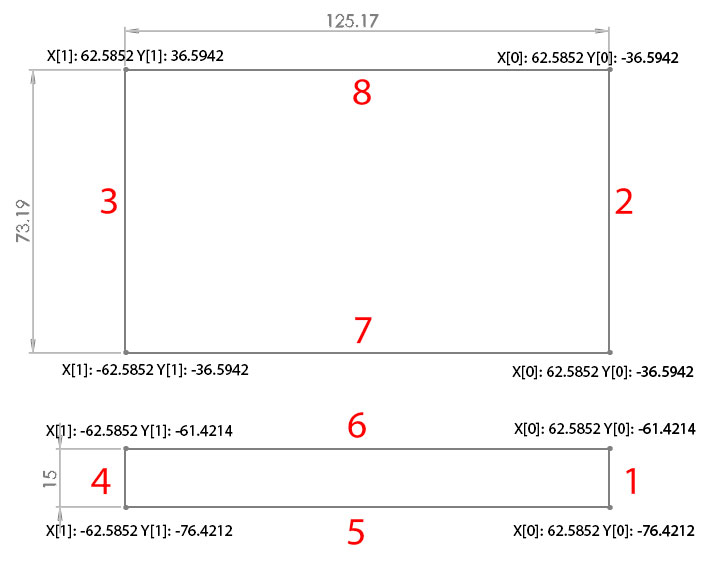
Now, I realized that the even lines contains the horizontal segments while the odds lines contains the vertical segments, but I cannot rely on this statement since there can be different shapes.
My problem now is to understand what's the better way to create a list of x,y points related to only the horizontal lies and another list that contains only the vertical lines order starting from the lowest coordinate.
The robot will move by firstly print the vertical lines and then all the horizontal lines.
In the figure below, for example, the robot will first print line 1, 2, 3, 4 and it will stop and then it will print lines 5, 6, 7, 8.
So, I need to communicate to the robot all the waypoints in the correct order.
What is the best way to create these two groups and order each lines based on their distance? The robot needs to optimize the path by firstly print all the segments that belong to the same direction.
dwg_SQUARES.jpg
I was able to successfully create a std::vector which contains a struct with four x,y points in this way:
struct Coordinate
{
    double x0, x1, y0, y1;

    Coordinate(double paramx0, double paramy0, double paramx1, double paramy1) : x0(paramx0), y0(paramy0), x1(paramx1), y1(paramy1) {}
};

std::vector<Coordinate> coords;Each row in the vector is filled in this way:
coords.push_back(Coordinate(global_x0, global_y0, global_x1, global_y1));and I print it as:
cout<<coords.size()<<endl;

for (unsigned int i = 0; i < coords.size(); ++i)
{
   cout << i << " X[0]: " << coords[i].x0 << " Y[0]: " << coords[i].y0 << " || X[1]: " << coords[i].x1 << " Y[1]: " << coords[i].y1 << endl;
}this is the output I get:
0 X[0]: 62.5852 Y[0]: -36.5942 || X[1]: -62.5852 Y[1]: -36.5942
1 X[0]: 62.5852 Y[0]: -36.5942 || X[1]: 62.5852 Y[1]: 36.5942
2 X[0]: 62.5852 Y[0]: 36.5942 || X[1]: -62.5852 Y[1]: 36.5942
3 X[0]: -62.5852 Y[0]: -36.5942 || X[1]: -62.5852 Y[1]: 36.5942
4 X[0]: 62.5852 Y[0]: -76.4212 || X[1]: -62.5852 Y[1]: -76.4212
5 X[0]: 62.5852 Y[0]: -76.4212 || X[1]: 62.5852 Y[1]: -61.4214
6 X[0]: 62.5852 Y[0]: -61.4214 || X[1]: -62.5852 Y[1]: -61.4214
7 X[0]: -62.5852 Y[0]: -76.4212 || X[1]: -62.5852 Y[1]: -61.4214
for this figure:
Now, I realized that the even lines contains the horizontal segments while the odds lines contains the vertical segments, but I cannot rely on this statement since there can be different shapes.
My problem now is to understand what's the better way to create a list of x,y points related to only the horizontal lies and another list that contains only the vertical lines order starting from the lowest coordinate.
The robot will move by firstly print the vertical lines and then all the horizontal lines.
In the figure below, for example, the robot will first print line 1, 2, 3, 4 and it will stop and then it will print lines 5, 6, 7, 8.
So, I need to communicate to the robot all the waypoints in the correct order.
What is the best way to create these two groups and order each lines based on their distance? The robot needs to optimize the path by firstly print all the segments that belong to the same direction.
dwg_SQUARES.jpg
ASKER
As suggested, I was able to write a struct to store the coordinates values and a std::vector to contain all of them.
Thank you.
Thank you.
the even lines contains the horizontal segments while the odds lines contains the vertical segmentswhat do you mean by 'even' and 'odd' lines and how could a line contain a horizontal or vertical segment?
i still do not know what is the meaning of the rectangles and the black or grey line segments.
Sara
ASKER
@sarabande: may be I didn't explain it better, let's look at this list of coordinates:
0 X[0]: 62.5852 Y[0]: -36.5942 || X[1]: -62.5852 Y[1]: -36.5942
1 X[0]: 62.5852 Y[0]: -36.5942 || X[1]: 62.5852 Y[1]: 36.5942
2 X[0]: 62.5852 Y[0]: 36.5942 || X[1]: -62.5852 Y[1]: 36.5942
3 X[0]: -62.5852 Y[0]: -36.5942 || X[1]: -62.5852 Y[1]: 36.5942
4 X[0]: 62.5852 Y[0]: -76.4212 || X[1]: -62.5852 Y[1]: -76.4212
5 X[0]: 62.5852 Y[0]: -76.4212 || X[1]: 62.5852 Y[1]: -61.4214
6 X[0]: 62.5852 Y[0]: -61.4214 || X[1]: -62.5852 Y[1]: -61.4214
7 X[0]: -62.5852 Y[0]: -76.4212 || X[1]: -62.5852 Y[1]: -61.4214
We have 0, 2, 4, 6 even lines and 1, 3, 5, 7 odds lines.
Now, each lines contains 4 coordinates: x0, y0, x1, y1.
A segment is described by a set of two coordinates (x1-x0), (y1-y0).
However, I opened another question since I was able to correctly find the segments and check if they are parallel to the X or Y axis, but I'm having problems with std:vector, sorting and removing the duplicates.
EDIT1: the black lines are the segments that compose the rectangles, the grey lines are for measurement references and they shouldn't be considered.
EDIT2: I modified the new question by adding a short explaination on how the segments are identified.
ok. even and odd is just the property of the zero-based index (which is fixed by the order the lines defined in the text file. so you can't really trust on it beside you would check it while parsing the line definitions. it corresponds to even == horizontal and odd == vertical, right?
i think you should forget the lines if it is granted that the rectangles itself have horizontal lines which are parallel to x-axis. then, necessarily the vertical lines are parallel to the y-axis of a coordinate system. if so, any of your rectangles fully is determined by two points, i. e. by 4 coordinates (x-left, y-top, x-right, y-bottom). using c++ you could describe your entity model in a header file like the following.
Sara
i think you should forget the lines if it is granted that the rectangles itself have horizontal lines which are parallel to x-axis. then, necessarily the vertical lines are parallel to the y-axis of a coordinate system. if so, any of your rectangles fully is determined by two points, i. e. by 4 coordinates (x-left, y-top, x-right, y-bottom). using c++ you could describe your entity model in a header file like the following.
#ifndef ROBOT_H
#define ROBOT_H

#include <vector>
#include <string>

// a structure that holds data and has no functionality
// would be a struct rather than a class
// in a struct all members are public (if not explicitly told differently by using private: or protected:)
struct Point
{
    int x, y;
    // this creates both a default constructor and a consttor to set all members
    // default constructors are necessary if you want to use containers with an initial size of items
    Point(int a = 0, int b = 0) : x(a), y(b) {}
};

struct Rectangle
{
    // use coordinates rather than points to define a rectangle.
    // advantage
    int left, top, right, bottom;

    // order coordinates from left to right and from top to bottom
    void OrderCoords()
    {
        if (left > right) { std::swap( left, right); }
        if (top > bottom) { std::swap(top, bottom); }
    }
    Rectangle(int x1 = 0, int y1 = 0, int x2 = 0, int y2 = 0)
        : left(x1), top(y1), right(x2), bottom(y2) { OrderCoords();}
    Rectangle(Point pt1, Point pt2)
        : left(pt1.x), top(pt1.y), right(pt2.x), bottom(pt2.y) { OrderCoords(); }
    int Width() const { return right - left; }
    int Height() const { return bottom - top; }
    bool Intersect(const Rectangle & r)
    { // check if one of the rectangles is left or above
        if (r.right < left || right < r.left || r.top > bottom || top > r.bottom)
        {
            return false;
        }
        return true;
    }
    Point TopLeft() { return Point(left, top); }
    Point TopRight() { return Point(right, top); }
    Point BottomLeft() { return Point(left, bottom); }
    Point BottomRight() { return Point(right, bottom); }
};

typedef unsigned int RGB;

struct ColoredRectangle : public Rectangle
{
    RGB color;
    ColoredRectangle(int x1 = 0, int y1 = 0, int x2 = 0, int y2 = 0, RGB col = 0xffffffff)
        : Rectangle(x1, y1, x2, y2), color(col) {}
    ColoredRectangle(Point pt1, Point pt2, RGB col = 0xffffffff)
        : Rectangle(pt1.x, pt1.y, pt2.x, pt2.y), color(col) {}
};

class Layer
{
    std::vector<ColoredRectangle> rectangles;
public:
    int AddColoredRectangle(const ColoredRectangle & crt) { rectangles.push_back(crt); }
    int GetNumRectangles() const { return (int)rectangles.size(); }
    ColoredRectangle GetRectangle(int index) const { return (index < 0 || index >= GetNumRectangles()) ? ColoredRectangle() : rectangles[index]; }
};

class LayerSystem
{
    std::vector<Layer> layers;
public:
    bool Load(const char * textfile);
    int  GetNumLayers() const { return (int)layers.size(); }
    Layer GetLayer(int index) const { return (index < 0 || index >= GetNumLayers()) ? ColoredRectangle() : layers[index]; }
}; Sara
yoiu easily can see that because the first rectangle has coordinates
top-left = (-62.582, 36.5942)
top-right = (+62.582, 36.5942)
bottom-right = ( 62.582, -36.5942)
bottom-left = (-62.582, -36.5942)
Sara