Home Security
--
Questions
--
Followers
Top Experts
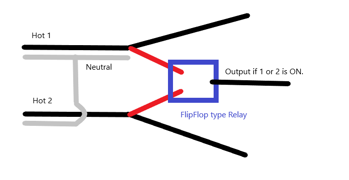
I've got two 120V lines coming from breaker panel. Circuit A is power to the outdoor flood lights, Circuit B is power to the garage door opener, which powers its own lights. I want to install a 3rd set of lights under the eaves in front of the garage that will be turned on if either the outdoor flood lights are on or the garage door opener lights are on.
The intent is to get plenty of light in front of the garage when the door is opened or to provide as much light as possible if the flood lights are on without the two existing circuits bleeding over into each other and all the lights coming on.
Zero AI Policy
We believe in human intelligence. Our moderation policy strictly prohibits the use of LLM content in our Q&A threads.
sw1
or circuit powers relay that applies power to new set of lights
sw2
The concept isn't very tough. I've done a lot of wiring over the years but this is the first time that this has come up. I seems like a normal thing to want to do so I'm wondering why I can't find readily available solutions.
Drive the new set of lights with an X-10 receiver on the same channel as the two control modules.


EARN REWARDS FOR ASKING, ANSWERING, AND MORE.
Earn free swag for participating on the platform.
Do the flood lights include an external outlet?
The straight forward your door opener circuit is a 20Amp circuit extending it pre-garage door opener should be enough and all you need for the additional lights is a motion sensor.
Often, extending the power from the flood lights which are already at the wall.
You might want to add lights to the garage door triggered illumination and half along the flood lights route to achieve the best of both worlds.
I'm looking to install some under-eave lighting to augment the existing lighting. There are woods directly behind the garage and a biker bar is the first thing on the other side of the woods. A couple of LED ceiling lights will light up the garage entrance just fine. If controllable by both circuits they will also help light up everything when the floods are on. The lights are cheap enough that I could install 4, connecting 2 to each circuit, but that winds up looking quite odd.
to activate/deactivate the light on/off event
The power on/off based on garage door activator is fairly straight forward as it has/includes the light that are turned on and off when the door it opened and closed.
The floods rely on a motion sensor I suspect, and that commonly means the floods have to have an outlet controlled by the motion sensor.
using relays that are remotely activated
ie. garage door opens, the relay connected there triggers the event ..
garage door close...
Distances and things are what come to mind
See examples with rfid and relays.
https://www.amazon.com/rf-relay/s?k=rf+relay
Get a FREE t-shirt when you ask your first question.
We believe in human intelligence. Our moderation policy strictly prohibits the use of LLM content in our Q&A threads.
The relay is not the issue, you want two different actuators to turn it on and be on if both are on.
Your post garage door openner is still 120V feed
you could have a step down feed from the 120V to 12 DC to go towards the relay as you depict that can tolerate a draw of 12-24V on the switching side @15ma.
You have two triggering options
Garadoor Flood lights actuator
0 0 0
0 1 1
1 0 1
1 1 1
https://www.amazon.com/Electronics-Salon-SPST-NO-Module-Control-Voltage/dp/B01B60RZPA/ref=sr_1_1_sspa?dchild=1&keywords=24v+120v+relay&qid=1632774206&sr=8-1-spons&psc=1&spLa=ZW5jcnlwdGVkUXVhbGlmaWVyPUExS0NIWEczQTVJQ0QmZW5jcnlwdGVkSWQ9QTA1NjE5MzkzNzJLWE43MUJHQjZMJmVuY3J5cHRlZEFkSWQ9QTAwMjExNTMyUkJQUVdZVEdHSEhaJndpZGdldE5hbWU9c3BfYXRmJmFjdGlvbj1jbGlja1JlZGlyZWN0JmRvTm90TG9nQ2xpY2s9dHJ1ZQ==
One position and primary is post garage door feed, if there is no power, it auto switches to the other position.
This way when both are on, only the primary circuit will be active.
Power from garage door ====>*
* <==feed to set of lights
Power from flood light source ====>>*
The swing of connector is controlled by power on the primary designated live.
I.e. Garage door open, relay triggers closes that circuit, garage door closed, the relay falls back closing the other circuit without regard on whether it is powered or not.
EARN REWARDS FOR ASKING, ANSWERING, AND MORE.
Earn free swag for participating on the platform.
of you need to have a ground (green) to avoid overloads.....
The device I'm looking for (the blue box) was a simple flip-flop back when most parts were mechanical. 240V won't happen since the flip-flop will connect the output to either input but not both simultaneously.
Both of the relays you linked require a low-voltage control circuit. I want to avoid that. (Actually bought one of them, but decided to go another direction.)
But the power backup switch sounds interesting. I hadn't consider that until now. Gonna investigate! :)
The max rating on no nc and common is 30Amp @240
If you feed 120 120 cones out
If you have a 120V relay with a 12 volt trigger, you could use a ac to DC adapter that has 12 volt. Usually it needs to draw 25 milliamperes through the solenoid to switch from normally closed position to the normally open circuit.
Get a FREE t-shirt when you ask your first question.
We believe in human intelligence. Our moderation policy strictly prohibits the use of LLM content in our Q&A threads.
I took 30A/14V to mean a 14V control circuit.
Description of item a lamp on the circuit ...
Tnisesm 2PCS Power Relay AC120V Coil, 30A SPDT(1NO 1NC) 120 VAC w
Zoom over the unit. 3rd row of text on the right.
EARN REWARDS FOR ASKING, ANSWERING, AND MORE.
Earn free swag for participating on the platform.
50/60 HZ 30A/240
30A/14V DC
-120vAC
I think the first two describe the max wattage through the nc/no comm terminals.
That 30A/14v make o sense. Usually, actuator circuit provide voltage and ii alike ape rage need to actuate.
30Amp from a 14 V source has more sense to be a max rating for flow, versus for the actuator circuit info.
Some of the exchanges with the seller, has a clarification that this relay is a 120v actuator
The relay, circuit, document/usage I gt clarify.
https://www.digikey.com/en/products/detail/picker-components/PTRA-1C-120S-T5-X/12318142?utm_adgroup=&utm_source=bing&utm_medium=cpc&utm_campaign=Shopping_DK%2BSupplier_Other&utm_term=&utm_content=&utm_id=bi_cmp-384720322_adg-1306220140326442_ad-81638827568289_pla-4585238372516895_dev-c_ext-_prd-12318142&msclkid=9d0e2beb80d014f430234ab8dcbe198a
The actuator seems to be an AC120 with 16.5ma accross the circuit to activate.
Connecting a USB charger might be enough to generate a 16.5ma leak when the whatever you connect to the NO terminal is turned on, and ...
The main thrust of your need is a relay that can handle the 120V and the amperage through the relay.30/40AMP is a bit much based on your description.
But I think you are cloer o the electrical side. the placement of the wires or the connecting .....
The location from which you want to extend the lights. does it have its own power source?
i.e. a though of a remote RFID type of activator.
Similr to a car door opener. press one on, press two off using relays to generate a pulse ....
- The location from which you want to extend the lights. does it have its own power source?i.e. a though of a remote RFID type of activator.
Get a FREE t-shirt when you ask your first question.
We believe in human intelligence. Our moderation policy strictly prohibits the use of LLM content in our Q&A threads.
Does the flood light have an outlet ?
See whether some garage openers might have a lower output i.e. a 48/24 volt
you could test the relays without the need to run wires...as a test with one bulb..
getting the relays and testing their functionality before..
running the wires, have to go under driveway to the other side?
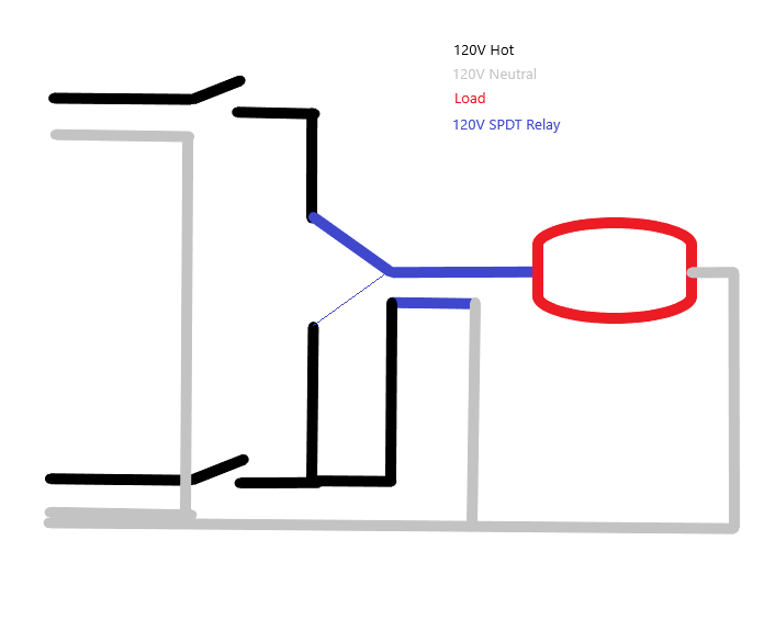
With both switches off, the relay activates the top circuit. When the top switch is turned on, the lights (load) are turned on.
When the bottom switch is turned on, the relay changes to the other input and again, the light is turned on.
When both switches are on, the voltage from the top switch terminates and the bottom circuit powers the load.
The Neutral does not connect to the hot at the bottom of the picture. :) And the thin blue light represents the alternate connection.
The relay draws power only when the lower switch is on (and the lights).
It might take me a little while to actually get in the attic and wire all this up, but I feel good about it!
Thanks for helping talk me through this!
Personally, I would have the relay in an accessible location, on the outside in a weather proof box for easy replacement should the relay blow for any reason..
EARN REWARDS FOR ASKING, ANSWERING, AND MORE.
Earn free swag for participating on the platform.
Both lines are in the attic over the garage, about 15 feet apart, and the attic access only a few feet away. I was thinking of putting it in the attic. Now I'm thinking you're right and next to the switch that's in the garage is better. I'll still have to crawl through the attic to wire it up, but if I do it right any additional maintenance will be at standard wall switch height.
Thanks again!
Kent
Home Security
--
Questions
--
Followers
Top Experts
Home security includes the hardware and software in place to monitor and protect property, and personal security practices. The hardware can include the doors, locks, alarm systems, lighting, motion detectors, and cameras systems; the software can include applications connected to smart systems in your home or business or electronic surveillance systems provided by vendors. Personal security practices would be ensuring doors are locked, alarms activated, windows closed and many other routine tasks which act to prevent misfortunes.