Hardware
--
Questions
--
Followers
Top Experts
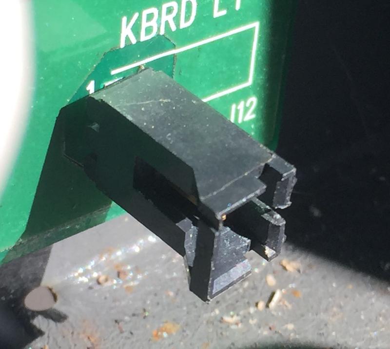
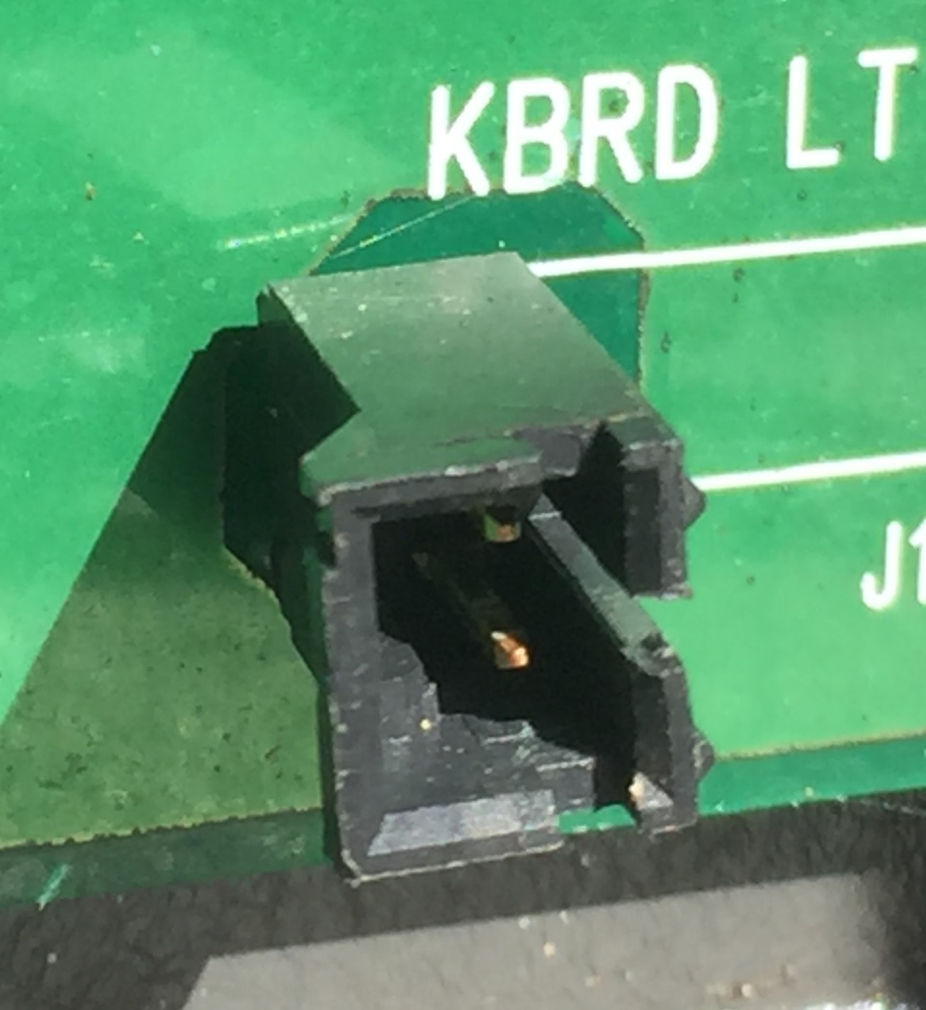
2-pin wire to board connector identification
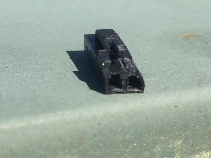
Maybe someone will recognize this connector. I need the plug end.
It's a rather tiny 2-pin connector for a 12-volt lighting fixture - similar to what one might find in a PC or... ?
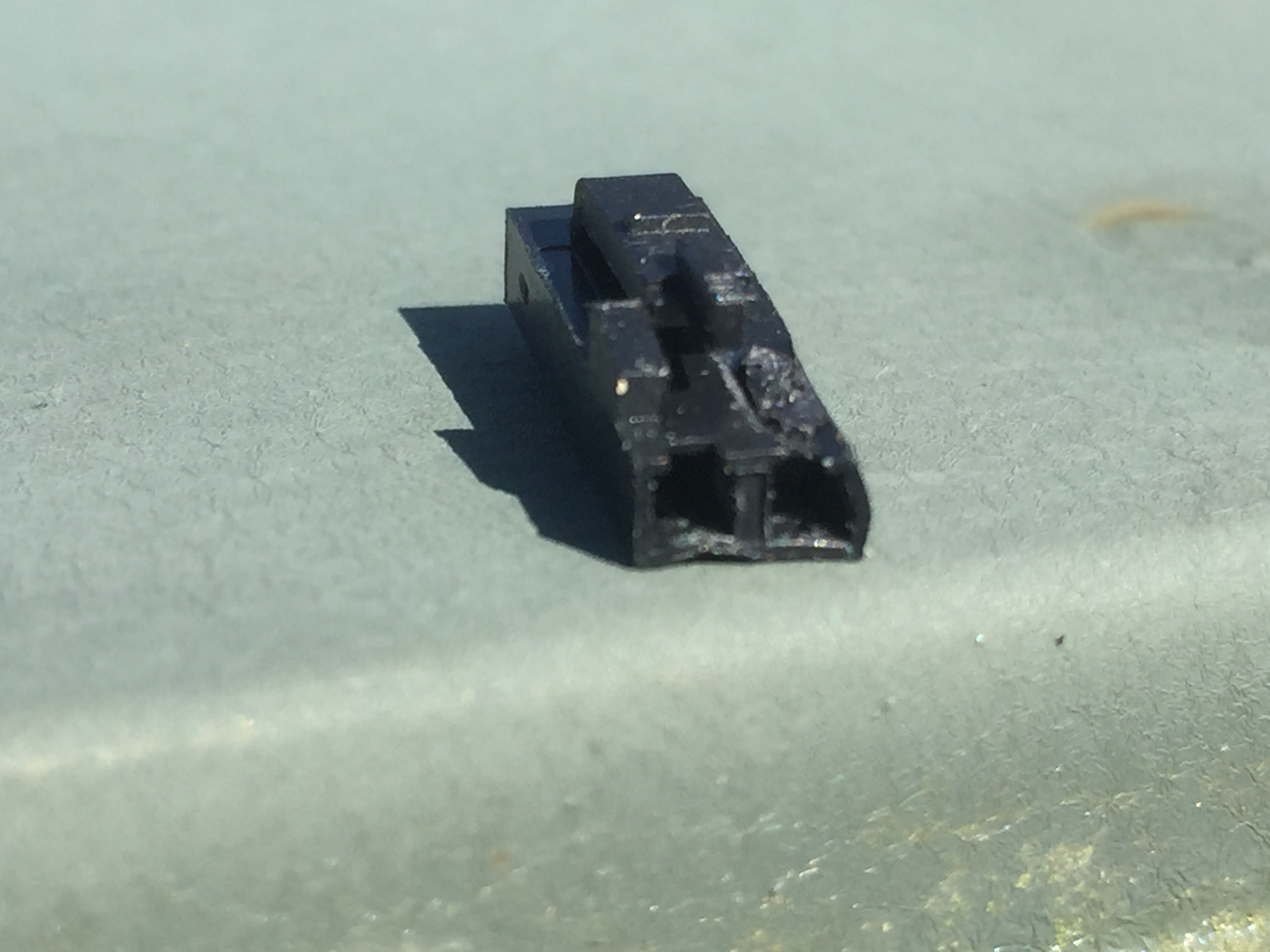
It's a locking connector with a squeeze-release on one side.
The plug measures very close to 0.2" wide and 0.1" high on the insertion end (plus appurtenances for the keying and the lock). It's 0.6" long.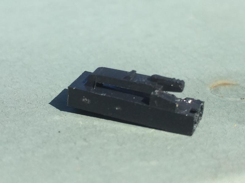
It's a rather tiny 2-pin connector for a 12-volt lighting fixture - similar to what one might find in a PC or... ?
It's a locking connector with a squeeze-release on one side.
The plug measures very close to 0.2" wide and 0.1" high on the insertion end (plus appurtenances for the keying and the lock). It's 0.6" long.


Zero AI Policy
We believe in human intelligence. Our moderation policy strictly prohibits the use of LLM content in our Q&A threads.
SOLUTION
membership
Log in or create a free account to see answer.
Signing up is free and takes 30 seconds. No credit card required.
SOLUTION
membership
Log in or create a free account to see answer.
Signing up is free and takes 30 seconds. No credit card required.
ASKER CERTIFIED SOLUTION
membership
Log in or create a free account to see answer.
Signing up is free and takes 30 seconds. No credit card required.
Good ideas all around! Thanks!
I stumbled onto the fact that Molex builds these LED circuit board strips that appear to include the connector.
Unfortunately, I believe that they're all custom designs. I have a couple of different ones on hand - neither one of which work.
They don't have much in the way of components,
- a couple SMT resistors R1 and R2 which appear to be 240 ohms and 430 ohms
- an SMT cap C1 marked 336v and 40H00
- a 4-lead IC with no markings. The power to the board comes into the two IC leads at one end. For all I know, it could be a pair of protective diodes. Or, it could be a full-wave diode bridge as these devices are said to run on either 12vdc OR 12vac. It appears these LED strips will run on 12vdc. if they are working.
There are 5 LEDs which look like they're connected in series - which surprises me a little.
The board is marked with small lettering DL-94V-0
And, with larger lettering: "chamberlain POP P/N 014B0932 REV A"
well, the POP may be POR - hard to tell.
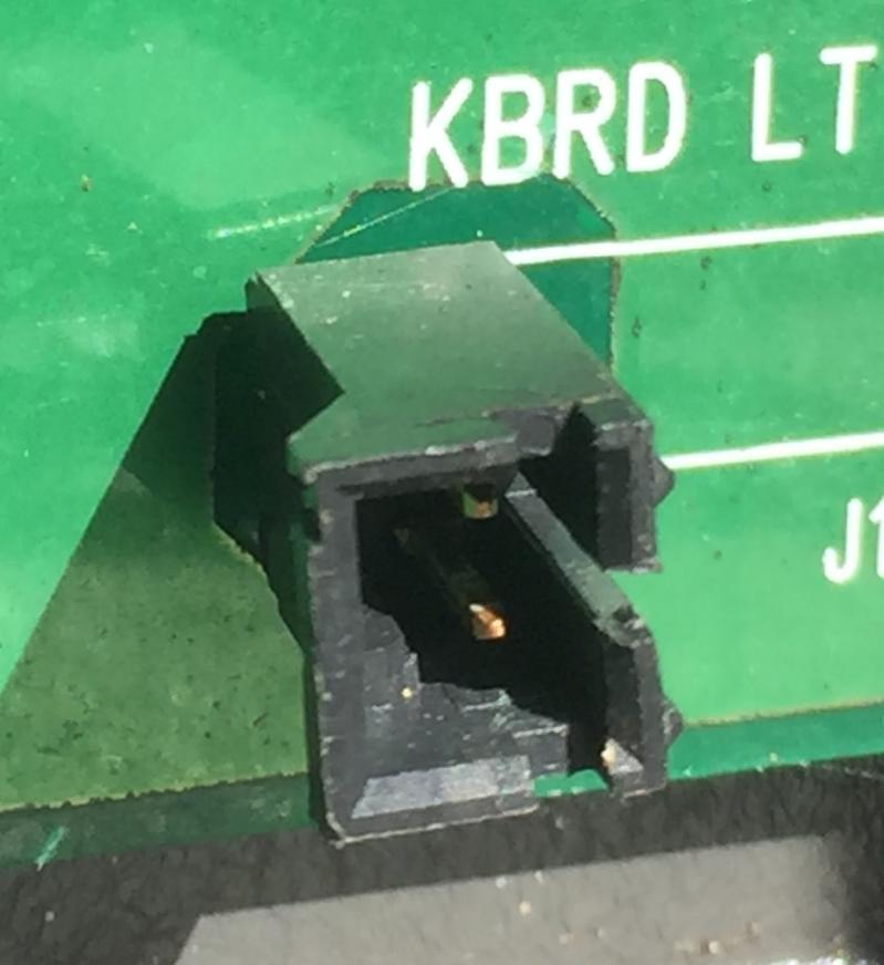
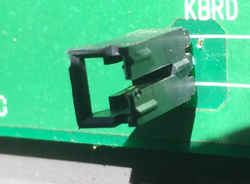
Here are a couple of pics of the board:

I'm providing this stuff with the idea that may be able to fix this board or even on the odd chance that I may find one - just to give a bigger picture. This is the lighting for an outdoor keypad that controls a residential gate. No spare parts.....
Thanks again!
I stumbled onto the fact that Molex builds these LED circuit board strips that appear to include the connector.
Unfortunately, I believe that they're all custom designs. I have a couple of different ones on hand - neither one of which work.
They don't have much in the way of components,
- a couple SMT resistors R1 and R2 which appear to be 240 ohms and 430 ohms
- an SMT cap C1 marked 336v and 40H00
- a 4-lead IC with no markings. The power to the board comes into the two IC leads at one end. For all I know, it could be a pair of protective diodes. Or, it could be a full-wave diode bridge as these devices are said to run on either 12vdc OR 12vac. It appears these LED strips will run on 12vdc. if they are working.
There are 5 LEDs which look like they're connected in series - which surprises me a little.
The board is marked with small lettering DL-94V-0
And, with larger lettering: "chamberlain POP P/N 014B0932 REV A"
well, the POP may be POR - hard to tell.
Here are a couple of pics of the board:


I'm providing this stuff with the idea that may be able to fix this board or even on the odd chance that I may find one - just to give a bigger picture. This is the lighting for an outdoor keypad that controls a residential gate. No spare parts.....
Thanks again!
Thanks again!
Since the (presumably filter) cap is located down at the other end of the board and the IC ("U1") is in the middle, my guess would be that it is a small rectifier bridge. 5 LEDs in series would be exactly right for 12 VDC - 2.0 to 2.4 volts each times 5 = 10 to 12 volts. The resistors are probably there for current limiting.
The components most likely to fail would be the 33 uF tantalum capacitor and the rectifier bridge. The LEDs should be testable on the board with the diode test setting on a DMM.
The components most likely to fail would be the 33 uF tantalum capacitor and the rectifier bridge. The LEDs should be testable on the board with the diode test setting on a DMM.


EARN REWARDS FOR ASKING, ANSWERING, AND MORE.
Earn free swag for participating on the platform.
There looks to be a dry joint on U1 directly below the "3" of LED3, of course it may be the light or dirt but it looks like it to me.
Hardware
--
Questions
--
Followers
Top Experts
Hardware includes cell phones and other digital living devices, tablets, computers, servers, peripherals and components, printers and scanners, gaming consoles, networking hardware such as routers, hubs, switches and modems, storage devices and security equipment such as firewalls and other appliances.